🔥 Join Free Webinar on Thermal Energy Storage!

Facts about Finite Element Method (FEM)

Finite Element Method (FEM)

Finite Element Method (FEM) or Finite Element Analysis (FEA) is a numerical method used for solving complex engineering problems. It is a powerful tool that enables engineers to analyze structures and systems to determine their performance under various conditions.

The Finite Element Method/Analysis solves partial differential equations that arise in engineering and physics. It involves dividing the problem domain into smaller, simpler regions called finite elements. These elements are then connected to form a mesh or a grid. The governing equations are solved for each element. Afterwards, the solutions are combined to obtain the overall solution for the system.

FEM/FEA is used in various fields of engineering, such as:

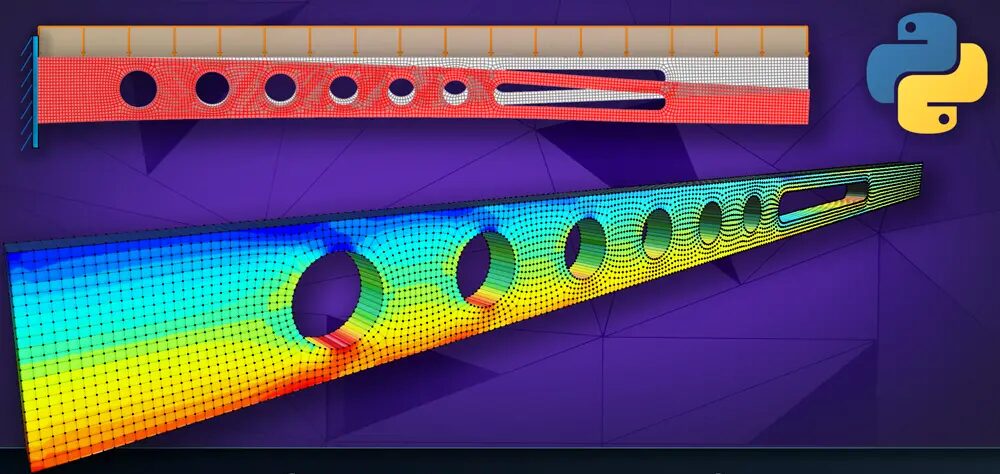
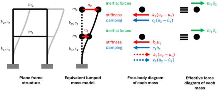
  • Structural Analysis: FEM/FEA is used to analyze the behavior of structures under different loading conditions. It is used to determine the stress and strain distribution in a structure, the deformation of the structure, and the natural frequencies of the structure.
  • Fluid Dynamics: FEM/FEA is used to solve fluid flow problems, such as calculating the pressure and velocity distribution in pipes, channels, and other flow systems.
  • Heat Transfer: FEM/FEA is used to analyze the heat transfer in various systems, such as heat exchangers, boilers, and furnaces.
  • Electromagnetics: FEM/FEA is used to analyze electromagnetic fields, such as those found in motors, transformers, and other electrical equipment.

FEM/FEA has become an essential tool in modern engineering design and analysis because it enables engineers to simulate complex physical systems and predict their behavior under various conditions. Need help with FEM / FEA Projects? Seek support from our exceptional engineers:

Related Articles

Simulating Renewable Energy Systems Using Simulink: A Practical Approach with Design a Large Battery Storage System

This MATLAB Simulink model presents the design and implementation of a Large Battery Energy Storage System (BESS) aimed at alleviating peak power demands in Colombo, Sri Lanka. The system utilizes grid-forming control to facilitate power injection during peak times and incorporates a battery management system (BMS) for efficient operation. Additionally, a photovoltaic (PV) system is integrated to supplement power generation. The model encompasses various components such as converters, filters, and controllers to regulate power flow and ensure seamless integration with the grid. Detailed simulations evaluate system performance, validating the effectiveness of peak shaving strategies and compliance with relevant industry standards like IEEE 1547-2018 and IEEE 2030.2.1-2019. Results indicate successful peak shaving functionality and highlight the impact of time delays on system dynamics.

Design and LTSpice Simulation of a High-Efficiency Bidirectional Single-Phase EV Charger for Vehicle-to-Grid (V2G) Applications

Author: Waqas Javaid

Introduction:

In this project, a groundbreaking single-phase bidirectional current-source AC/DC converter tailored for Vehicle-to-Grid (V2G) applications is unveiled. The converter is ingeniously designed; comprising a line frequency commutated unfolding bridge and an interleaved buck-boost stage. Notably, the semiconductor losses within the line frequency commutated unfolding bridge contribute to the converter’s commendable efficiency. The interleaved buck-boost stage further enhances performance with its dual capabilities of buck and boost operating modes, facilitating seamless operation across a broad battery voltage range [2]. The interleaved structure of this stage significantly reduces battery current ripple. Beyond these advantages, the converter ensures sinusoidal input current, bidirectional power flow, and the capability for reactive power compensation. This project delves into the intricate topology and operational principles of this innovative converter, shedding light on its potential impact in the realm of V2G applications.

Calibration and Design of High-Precision Sensor Systems for Optomechanical Applications

Author: Waqas Javaid

Abstract:

This MATLAB script presents a comprehensive framework for the calibration and design of high-precision sensor systems tailored for optomechanical applications. The script encompasses the calibration of cavity optomechanical displacement-based sensors, as well as the design considerations for accelerometers, force detection sensors, and torque magnetometry sensors. The calibration procedure involves processing sensor data, particularly from accelerometers and magnetometers, to derive accurate calibration parameters. A key aspect of the calibration process involves performing a spherical fit on the magnetometer data to determine the center, residue, and radius of the fitted sphere [1]. These calibration parameters are essential for ensuring the accuracy and reliability of sensor measurements.

The MATLAB script also includes simulations and visualizations to illustrate the calibration procedure and sensor design. Furthermore, the project incorporates Simulink models to simulate MEMS accelerometer systems, integrating force, translational dynamics, and voltage outputs. The resulting framework provides a comprehensive toolkit for sensor calibration, design, and simulation, contributing to advancements in high-precision sensor technologies. In addition to calibration, the script provides a platform for designing sensor systems suitable for various applications [2] [3]. Designs for accelerometers, force detection sensors, and torque magnetometer sensors are defined, considering parameters such as sensitivity, frequency range, and noise levels. These designs serve as a foundation for developing sensor systems tailored to specific operational requirements. The MATLAB code simulation also generates informative visualizations, including plots of sensor data, calibration results, and sensor designs. These visualizations aid in understanding the behavior and performance characteristics of the sensors, facilitating informed decision-making during sensor calibration and system design processes.

Obtaining the Inductance with Dependence on Frequency and Amplitude of the Applied Alternating Current via Measurements and Validation of Considered Non-linearity and Saturation Effects with Lumped Parameter Model

This publication provides the process for obtaining of a self-inductance of electrical machines with a dependence on frequency and amplitude of an applied alternating current and consideration of a non-linearity and saturation effects in the equivalent circuit lumped parameter model that would have the same frequency and time domain characteristic as some desired investigated electrical machine. The values of inductances were calculated from measured impedances for wide ranges of frequencies and currents according to the theory of a complex inductance and iron losses. The measured data were analyzed and summarized in a table and then used for modeling of a automotive alternator. The model was supplied with curve fitted data. The simulation of a common automotive test case was obtained and compared with measurements. Good match between the theory and measurements and reasonability of the suggested approach were confirmed.


This content is for Basic and Premium members only.
Join Now
Already a member? Log in here

Responses

Your email address will not be published. Required fields are marked *

L ading...