

Electric Circuits with emphasis on electrical Circuit Analysis
Introduction:
Circuit analysis has long been a traditional introduction to the art of problem solving from an engineering perspective, even for those whose interests lie outside electrical engineering. There are many reasons for this, but one of the best is that in today’s world it’s extremely unlikely for an engineer to encounter a system that does not in some way include electrical circuitry. As circuits become smaller and require less power, and power sources become smaller and cheaper, embedded circuits and seemingly everywhere.
Since most engineering situations require a team effort at some stage, having a working knowledge of circuit analysis therefore helps to provide everyone on a project with the background needed for effective communication.
Consequently, this article is just not about “circuit analysis” from an engineering perspective, but is also about developing basic problem-solving skills as they apply to situations an engineer is likely to encounter. As part of this, we also find that we’re developing an intuitive understanding at a general level, and we can understand a complex system by its analogy to an electrical circuit. Before launching into all this, however, we’ll begin with a quick preview of the topics found in the remainder of this article, pausing briefly to ponder the difference between analysis and design, and the evolving role computer tools play in modern engineering.
The fundamental subject of this article is linear circuit analysis, which sometimes prompts a few readers to ask,
“Is there ever any nonlinear circuit analysis?”
Sure! We encounter non-linear circuits everyday: they capture and decode signals for our TVs and radios, perform calculations millions of times per second inside microprocessors, convert speech into electrical signals for transmission over the telephone lines, and execute many other functions outside our field of view. In designing, testing, and implementing such nonlinear circuits, detailed analysis is unavoidable.
“They why study linear circuit analysis?”
You might ask. An excellent question. The simple fact of the matter is that no physical system (including electrical circuits) is ever perfectly linear. Fortunately for us, however, a great many systems behave in a reasonably linear fashion over a limited range – allowing them to model them as linear systems if we keep the range limitations in mind. For example, consider the common function
f(x) = ex
A linear approximation to this function is
f(x) = 1 + x
Linear problems are inherently more easily solved than their nonlinear counterparts. For this reason, we often seek reasonably accurate linear approximations (or models) to physical situations. Furthermore, the linear models are more easily manipulated and understood – making design a more straightforward process.
The circuits we will encounter next all represent linear approximations to physical electrical circuits. Where appropriate, brief discussions of potential inaccuracies or limitations to these models are provided, but generally speaking we find them to be suitably accurate for most applications. When greater accuracy is required in practice, nonlinear models are employed, but with a reasonably increase in solution complexity.
Linear circuit analysis can be separated into four broad categories: (1) dc analysis, where the energy sources do not change with time; (2) transient analysis, where things often change quickly; (3) sinusoidal analysis, which applies to both ac power and signals; and (4) frequency response, which is the most general of the four categories, but typically assume something is changing with time. We begin our journey with the topic of resistive circuits, which may include simple examples of a flashlight or a toaster. This provides us with a perfect opportunity to learn a number of very powerful engineering circuit analysis techniques, such as nodal analysis, mesh analysis, superposition, source transformation, Thevenin’s theorem, Norton’s theorem, and several methods for simplifying network of components connected in series or in parallel. The single most redeeming feature of resistive circuits is that the time dependence of any quantity of interest does not affect our analysis procedure. In other words, if asked for an electrical quantity of a resistive circuit at several specific instants in time, we do not need to analyze the circuit more than once. As a result, we will spend most of our effort early on considering only dc circuits – those circuits whose electrical parameters do not vary with time.
Although dc circuits such as flashlights or automotive rear window defoggers are undeniably important in everyday life, things are often much more interesting when something happens suddenly. In circuit analysis parlance, we refer to transient analysis as the suite of techniques used to study circuit which are suddenly energized or de-energized. To make such circuits interesting, we need to add elements that respond to the rate of change of electrical quantities, leading to circuit equations which include derivatives and integrals. Fortunately, we can obtain such equations using the simple techniques learned in the first part of our study.
Still, not all time varying circuits are tuned off and on suddenly. Air conditioners, fans, and fluorescent lights are only a few of the many examples we may see daily. In such situations, a calculus-based approach for every analysis can become tedious and time-consuming. Fortunately, there is a better alternative for situations where equipment has been allowed to run long enough for transient effects to die out, and this is commonly referred to as ac or sinusoidal analysis, or sometimes phasor analysis.
The final leg of our journey deals with a subject known as frequency response. Working directly with the differential equations obtained in time-domain analysis helps us develop intuitive understanding of the operation of circuits containing energy storage elements (e.g., capacitors and inductors). As we shall see, however, circuits with even a small number of components can be somewhat onerous to analyze, and so much more straightforward methods have been developed. These methods, which include Laplace and Fourier analysis, allow us to transform differential equations into algebraic equations. Such methods also enable us to design circuits to respond in specific ways to particular frequencies. We make use of frequency-dependent circuits every day when we dial a telephone, select our favorite radio station, or connect to the internet.
Relationship of Circuit Analysis to Engineering
Whether to intend to pursue further circuit analysis at the completion of this article or not, it is worth noting that there are several layers to the concepts under study. Beyond the nuts and bolts of circuit analysis techniques lies the opportunity to develop a methodical approach to problem solving, the ability to determine the goal or goals of a particular problem, skill at collecting the information needed to effect a solution, and, perhaps equally importantly opportunities for practice at verifying solution accuracy.
Students familiar with the study of other engineering topics such as fluid flow, automotive suspension systems, bridge design, supply chain management, or process control will recognize the general form of many of the equations we develop to describe the behavior of various circuits. We simply need to learn how to “translate” the relevant variables (for example, replacing voltage with force, charge with distance, resistance with friction coefficient, etc.) to find that we already know how to work a new type of problem. Very often, if we have previous experience in solving a similar or related problem, our intuition can guide us through the solution of a totally new problem.
What we are about to learn regarding linear circuit analysis forms the basis for many subsequent electrical engineering courses. The study of electronics relies on the analysis of circuits with devices known as diodes and transistors, which are used to construct power supplies, amplifiers, and digital circuits. The skills which we will develop are typically applied in a rapid, methodical fashion by electronics engineers, who sometimes can analyze a complicated circuit without even reaching for a pencil!
Electric circuits are the most analysis and design related things an electrical engineer face in daily life of an electrical engineer. There are different types of electrical circuits in electrical engineering. Some are linear and others are non-linear such as transistors and operational amplifier or “op amp” for short [1]. One of the basic circuit element is resistor. Its value is recorded in color code. Following color code is shown along with resistor to assist in decoding the original value of the resistors.
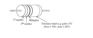
The Resistor Color Code
Band Color: Black Brown Red Orange Yellow Green Blue Violet Gray White
Numeric Value 0 1 2 3 4 5 6 7 8 9
- Write down the numeric value corresponding to the first band on the left side.
- Write down the numeric value corresponding to the second band from the left side.
- Write down the number of zeros indicated by the multiplier band, which represents the power of 10 (black = no extra zero, brown = 1 zero, red = 2 zeros etc.). A gold multiplier indicates that the decimal Is shifted to the one place on the left, a silver multiplier indicates that the decimal is shifted to the two places at the left.
- The tolerance band represents the precision. So, for example, we would not be surprised to find a 100 ohm 5 percent tolerance resistor that measures anywhere between the 95 ohm to 105 ohm.
Example
Red Red Orange Gold = 22000 or 22 x 103 = 22 k Ohm, 5% tolerance
Blue Gray Gold = 6.8 or 68 x 10-1 = 6.8 Ohm, 20% tolerance
Summary of basic op amp circuits include inverting amplifier, Non-inverting amplifier, Voltage follower (also known as a unity gain amplifier), summing amplifier, and difference amplifier.
References:
- William H. Hayt Jr., Jack E. Kemmerly, and Steven M. Durbin, Engineering circuit analysis, 8th 2012.


This is my first time pay a quick visit at here and i am really happy to read everthing at one place