

Direct Power Control Strategies for DFIG Wind Turbines: Implementation, Limitations, and Grid Disturbance Behavior in MATLAB

Author: Waqas Javaid
Abstract
Direct Power Control (DPC) represents an alternative approach to classical field-oriented control for doubly-fed induction generator (DFIG) wind turbines. Unlike vector control methods that employ inner current regulation loops, DPC operates directly on active and reactive power errors through hysteresis comparators and a switching table. This article examines the practical implementation of DPC for rotor-side converters in DFIG systems, with emphasis on converter-level behavior, switching frequency variability, and performance under non-ideal grid conditions. Instantaneous power calculation in the stationary αβ frame eliminates the need for coordinate transformations and current regulators, resulting in simplified structure and rapid transient response. However, variable switching frequency introduces challenges for filter design and thermal management. Simulation results demonstrate DPC behavior during grid voltage dips, weak grid operation, and distorted voltage conditions. Comparison with conventional vector control highlights the trade-offs between response speed, current quality, and implementation complexity. Practical constraints including sampling delay, measurement noise, and semiconductor limits are discussed. The article concludes with validation approaches for DPC implementation in wind energy systems.
Concept of Direct Power Control
Direct Power Control regulates active and reactive power directly at the converter terminals without intermediary current control loops. This distinguishes DPC fundamentally from classical field-oriented control (FOC) where power is controlled indirectly through current regulation in a synchronously rotating reference frame.
Fundamental Principle
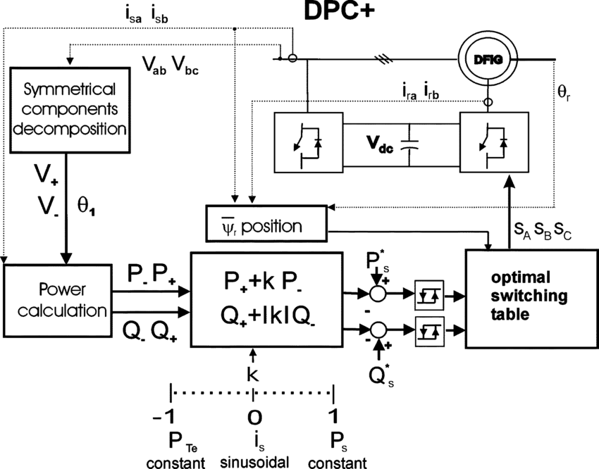
The core concept of DPC is straightforward: instantaneous active and reactive powers are calculated from measured voltages and currents, compared with reference values, and the errors are fed into hysteresis comparators. The comparator outputs, together with the angular position of the voltage vector, determine the appropriate switching state through a pre-defined lookup table. The converter switching devices are triggered directly, eliminating the need for pulse-width modulation (PWM) generators and current regulators [6].

For a two-level voltage source converter, eight switching states are available (six active vectors and two zero vectors). The selection logic aims to drive the power errors toward zero within a hysteresis band. When active power falls below the reference minus the hysteresis band, a switching state that increases power is selected; when it exceeds the reference plus the band, a state that decreases power is applied. The same principle applies to reactive power, creating a coupled decision process managed by the switching table.
Motivation for DPC Adoption
DPC emerged from the need for faster transient response and reduced parameter sensitivity compared to vector control. In FOC systems, the cascaded structure with inner current loops and outer power loops introduces phase lag and limits bandwidth. PI regulator tuning requires accurate machine parameters, and performance degrades when parameters deviate from nominal values.
DPC addresses these limitations through several mechanisms. First, eliminating current regulators removes the associated tuning effort and parameter dependence. Second, direct power regulation achieves response times limited only by switching device capabilities and sampling frequency [4]. Third, the hysteresis-based approach inherently accommodates nonlinearities and saturation effects without additional compensation.
The structural simplification is substantial: a complete DPC implementation requires approximately 30-40% fewer blocks than an equivalent FOC system. This reduction in complexity translates to lower computational load on control processors and simplified software validation.
Power Estimation and Reference Frames
Instantaneous Power Calculation
DPC operates on instantaneous power quantities calculated in the stationary αβ reference frame. For a three-phase system, the instantaneous active and reactive powers are given by:

where vα, vβ and iα, iβ are the voltage and current components obtained through Clarke transformation:

The factor 3/2 arises from the power-invariant transformation convention. These calculations are performed at each sampling instant using the most recent measurements.
αβ Frame vs. dq Frame
The choice of αβ frame over dq frame is fundamental to DPC operation. In vector control, the dq frame rotates synchronously with the stator flux or grid voltage, transforming AC quantities to DC values that can be regulated with PI controllers. This rotation requires accurate knowledge of the flux or voltage angle, typically obtained through phase-locked loops (PLLs) or flux estimators.
DPC remains in the stationary αβ frame for two reasons. First, the instantaneous power equations are simpler and require no angular information beyond the voltage vector position used for sector determination. Second, avoiding rotational transformations eliminates PLL dynamics and associated delays, contributing to faster transient response.
The voltage vector angle is still needed for sector identification, but this calculation uses only the atan2 function of the αβ voltage components and does not require phase tracking over multiple cycles.
Sampling Frequency Constraints
DPC performance depends critically on sampling frequency. The hysteresis comparators and switching table operate on sampled measurements, and the time between samples determines the minimum achievable response time. Typical sampling frequencies for DPC implementations range from 20 kHz to 100 kHz, substantially higher than the 5-10 kHz sampling used in vector control with PWM.
Higher sampling frequencies improve power tracking accuracy and reduce the average power error but increase computational burden and may require faster analog-to-digital converters. The relationship between sampling frequency and power ripple is approximately inverse: doubling the sampling frequency halves the time before error detection and correction, reducing the magnitude of power excursions beyond the hysteresis band.
Measurement Noise Influence
Noise on voltage and current measurements propagates directly into power calculations and can cause spurious switching events. The derivative nature of the hysteresis comparator makes it particularly sensitive to high-frequency noise, which may trigger unnecessary switching and increase losses.
Practical implementations employ analog anti-aliasing filters before sampling and digital filtering after conversion. However, filtering introduces phase delay that affects the apparent timing of power errors relative to the actual system state. The trade-off between noise rejection and phase delay must be carefully managed, typically with filter cutoff frequencies an order of magnitude above the expected switching frequency.
Digital Delay Impact
The interval between measurement sampling and switching state application creates a inherent delay in digital implementations. During this computation time, the system state evolves, and the switching decision based on delayed information may no longer be optimal.
For a sampling period Ts, the total delay from measurement to output is typically 1.5Ts to 2Ts, accounting for sampling, computation, and gate drive propagation. This delay effectively adds phase lag to the control loop and can lead to increased power ripple or instability at high switching frequencies. Compensation techniques include predictive algorithms that estimate the system state at the switching instant based on the system model and measured derivatives [1] [2].
Switching Logic and Control Structure
Hysteresis Controllers
The hysteresis comparator is the decision element in DPC. For active power, the comparator operates as:

where Hp is the hysteresis band for active power. The reactive power comparator Sq operates identically with band Hq. The hysteresis bands define the allowable power error before corrective action is taken.
The width of the hysteresis band directly affects system behavior. Narrow bands produce smaller steady-state power ripple but increase switching frequency, raising losses and thermal stress. Wide bands reduce switching frequency and losses but allow larger power excursions and may cause visible torque pulsations. Typical bands range from 1% to 5% of rated power.
Switching Tables
The switching table maps the combination of hysteresis outputs (Sp, Sq) and the voltage vector sector to a specific converter switching state. The sector is determined by the angle of the stator voltage vector:

The voltage plane is divided into 12 sectors of 30° each, providing sufficient resolution for vector selection. The switching table is designed to select vectors that increase or decrease active and reactive power according to the error signs.
Table 1 presents a typical switching table for DFIG rotor-side converter DPC. The table entries correspond to switching states [a b c] where 1 indicates the upper switch conducting and 0 the lower switch conducting.
Table 1: DPC Switching Table for 12-Sector Operation
| Sp | Sq | Sector 1 | Sector 2 | Sector 3 | Sector 4 | Sector 5 | Sector 6 | Sector 7 | Sector 8 | Sector 9 | Sector 10 | Sector 11 | Sector 12 |
| 0 | 0 | 000 | 000 | 000 | 000 | 000 | 000 | 000 | 000 | 000 | 000 | 000 | 000 |
| 0 | 1 | 010 | 011 | 001 | 101 | 100 | 110 | 010 | 011 | 001 | 101 | 100 | 110 |
| 1 | 0 | 110 | 010 | 011 | 001 | 101 | 100 | 110 | 010 | 011 | 001 | 101 | 100 |
| 1 | 1 | 001 | 101 | 100 | 110 | 010 | 011 | 001 | 101 | 100 | 110 | 010 | 011 |
The zero vectors (000, and optionally 111) are used when both power errors are within bands, reducing switching losses during steady-state operation.
Switching Frequency Variation
Unlike PWM-based methods with fixed carrier frequency, DPC produces variable switching frequency that depends on operating conditions. Factors influencing instantaneous switching frequency include:
- Hysteresis band width: Narrow bands increase frequency
- Power level: Higher power levels typically increase frequency
- Machine speed: Rotor voltage magnitude affects vector effectiveness
- Grid conditions: Disturbances cause frequency excursions
Typical DPC implementations exhibit switching frequencies ranging from 2 kHz to 15 kHz over the operating range. This variation complicates filter design, as output filters must attenuate harmonics across a wide frequency spectrum rather than at a fixed carrier frequency and its multiples.
Trade-off Between Ripple and Losses
The hysteresis bands represent the primary design trade-off in DPC. Narrow bands minimize power ripple and improve current quality but increase switching frequency and semiconductor losses. Wide bands reduce losses but degrade power quality and may cause unacceptable torque pulsations in the generator.
For a given application, the bands are selected to satisfy both power quality requirements (grid code compliance) and thermal constraints of the semiconductor devices. The relationship is approximately:

where k is a machine-dependent constant, H is the hysteresis band, Vdc is DC-link voltage, and Lσ is leakage inductance. This inverse relationship means that halving the band doubles the switching frequency.
Practical Switching Constraints
Semiconductor Limits
Power semiconductor devices (IGBTs) have maximum current, voltage, and junction temperature ratings that constrain DPC operation. The variable switching frequency characteristic of DPC complicates thermal design because losses cannot be predicted as simply as with fixed-frequency PWM.
Switching losses in IGBTs are approximately proportional to switching frequency and current. For a given device, the maximum allowable junction temperature determines the acceptable combination of conduction loss and switching loss. DPC implementations must include thermal monitoring or conservative band selection to prevent device overheating under worst-case conditions [1].
Thermal Stress
The non-uniform distribution of switching events in DPC creates thermal cycling that differs from PWM operation. Periods of high power demand or grid disturbance may produce bursts of high-frequency switching, causing rapid temperature rise. The thermal time constants of the silicon die and module package determine whether such bursts remain within safe operating limits.
Active thermal management techniques, such as temporarily widening hysteresis bands during overload conditions, can protect devices while maintaining control. However, this degrades power quality during the very conditions where accurate control is most needed.
DC-Link Voltage Dependency
The effectiveness of each voltage vector in changing power depends on the DC-link voltage magnitude. Higher DC voltage produces larger voltage steps at the converter output, accelerating power changes but potentially causing overshoot. The switching table assumes nominal DC voltage; significant variations alter the vector magnitudes and may degrade performance [2].
Rotor-side DPC in DFIG systems must coordinate with grid-side converter control to maintain DC-link voltage within acceptable bounds. During transients, DC voltage fluctuations affect the available rotor voltage and may temporarily reduce control authority.
You can download the Project files here: Download files now. (You must be logged in).
Overcurrent Protection Interaction
DPC lacks explicit current regulation, so overcurrent protection must be provided separately. Hysteresis comparators acting on power errors do not directly limit currents; a large power error could theoretically command switching states that produce excessive currents [3].
Practical implementations include additional current monitoring with fast hardware comparators that override switching commands if currents exceed safety thresholds. This protection layer must coordinate with the DPC logic to prevent nuisance trips while ensuring device safety. The coordination is typically implemented at the gate drive level with independent current sensing.
Behavior Under Non-Ideal Conditions
Grid Voltage Dips
Voltage dips represent one of the most challenging conditions for DPC operation. When grid voltage magnitude decreases, the relationship between switching states and power changes is altered. The same vector that increased power under nominal voltage may be less effective or even counterproductive during a dip.
DPC responds to voltage dips through its inherent fast action. As soon as the power error exceeds the hysteresis band due to the disturbance, the switching table selects vectors appropriate for the current conditions. The response time is limited only by sampling and switching delays, typically within 1-2 sampling periods [4].
However, the switching table optimized for nominal operation may not be optimal during deep voltage sags. Advanced DPC implementations incorporate voltage magnitude information into the vector selection process, either through adaptive tables or by scaling the hysteresis bands proportionally to voltage.
Compared to current-controlled systems, DPC typically achieves faster initial response to voltage dips but may exhibit larger current spikes because the power-based logic does not directly limit currents. The absence of current regulation means that during the first few switching periods after a dip, currents can rise rapidly until the power error integrates sufficiently to trigger corrective action.
Rapid Torque Variation
Mechanical torque variations from wind gusts or tower shadow effects produce corresponding power reference changes. DPC tracks these variations with minimal phase lag because the power loop operates at switching frequency rather than the limited bandwidth of cascaded regulators [5].
For a step change in power reference, DPC typically achieves 90% of the new value within 2-3 switching periods, corresponding to 200-300 μs for typical implementations. Vector control with PWM and PI regulators requires 5-10 ms for similar response, limited by current regulator bandwidth and PWM carrier period.
Weak Grid Conditions
Weak grids with significant impedance affect DPC performance by introducing coupling between power variations and voltage magnitude/phase. When the converter injects power, the voltage at the point of common coupling changes, which in turn affects the power calculation and subsequent switching decisions.
This coupling can lead to instability in extreme cases because the power measurement includes the effect of the converter’s own action on grid voltage. The hysteresis comparator sees a combined effect of intended power change and grid voltage response, potentially causing incorrect decisions [6].
Solutions include using estimated grid voltage (excluding converter-induced drop) for power calculation or implementing additional stabilization terms in the switching logic. Some DPC variants employ virtual flux estimation to reduce sensitivity to grid impedance.
Distorted Voltage Waveforms
Harmonic distortion in grid voltage introduces corresponding oscillations in instantaneous power calculations. These oscillations can trigger spurious switching events if their magnitude exceeds the hysteresis band, increasing switching frequency and losses without contributing to useful power transfer.
For a grid with 5% fifth harmonic, the resulting power oscillation at six times fundamental frequency may reach several percent of rated power. If this exceeds the hysteresis band, the comparator will attempt to correct these oscillations, causing unnecessary switching.
Solutions include:
- Widening hysteresis bands beyond expected distortion levels
- Implementing notch filters on power measurements at harmonic frequencies
- Using fundamental-positive-sequence extraction for power calculation
The latter approach sacrifices some response speed for improved steady-state behavior in distorted grids.
DPC in DFIG Wind Turbines
Stator Grid Connection Implications
In DFIG systems, the stator connects directly to the grid while the rotor connects through the back-to-back converter. This configuration imposes specific requirements on rotor-side DPC that differ from full-power converter applications.
The rotor-side converter controls the rotor currents to achieve desired stator active and reactive power. The relationship between rotor quantities and stator power depends on machine parameters and operating point. For DPC implementation, this means that the switching table must account for the induction machine characteristics rather than simply applying vectors based on grid voltage alone.
Rotor Flux Dynamics
Rotor flux responds to applied rotor voltage with dynamics governed by rotor time constant. When a voltage vector is applied, the resulting rotor current change produces torque and power variations through interaction with the rotating stator field. The effectiveness of each vector depends on the relative orientation of rotor flux and applied voltage.
The standard DPC switching table for DFIG is derived from analysis of rotor flux trajectory under different voltage vectors. Vectors that increase rotor flux magnitude tend to increase reactive power, while vectors that advance rotor flux angle relative to stator flux increase active power. This coupling means that vector selection must consider both effects simultaneously.
Transient Rotor Current Spikes
During grid disturbances, the sudden change in stator voltage induces transient currents in the rotor circuit through transformer action. These currents can exceed the converter rating within microseconds, before DPC has time to respond.
Rotor-side DPC alone cannot prevent these spikes because they result from magnetic coupling rather than converter action [7].
Protection requires either:
- Fast hardware current limiting in the converter
- Crowbar circuits that short the rotor windings during severe events
- Series dynamic braking resistors
The coordination between DPC and protection circuits must ensure that the converter remains in control during recoverable disturbances while protecting devices during severe events.
Coordination with Grid-Side Converter
The grid-side converter maintains DC-link voltage and can contribute to reactive power support. DPC on the rotor side must coordinate with grid-side control to maintain overall system stability.
During transient events, both converters respond to the disturbance. The rotor-side DPC attempts to regulate stator power, while the grid-side converter regulates DC voltage. If their actions conflict, instability can result. For example, rotor-side action that increases rotor power during a voltage dip may draw energy from the DC link, causing DC voltage drop that the grid-side converter must correct.
Coordinated strategies include:
- Prioritizing DC voltage regulation during severe events
- Limiting rotor-side power commands during transients
- Implementing communication or feedforward between converters
Simulation and Validation Approaches
Time-Domain Simulation
DPC development relies heavily on time-domain simulation because the variable switching frequency and hysteresis nonlinearities preclude small-signal analysis. Simulation must capture switching events with sufficient temporal resolution to accurately represent power ripple and switching losses [8].
Typical simulation approaches include:
- Switching-level models: Detailed IGBT models with gate drive circuits, accurate for loss estimation and EMI studies but computationally intensive
- Averaged models: Represent switching effects through controlled voltage sources, faster but lose switching ripple information
- Piece wise linear models: Approximate machine behavior between switching events, balancing speed and accuracy
For DFIG DPC studies, switching-level simulation of 1-2 seconds of operation typically requires 10-30 minutes of computation time on desktop hardware. This limits the number of test cases but provides essential validation of switching behavior.
Hardware-in-the-Loop Testing
Hardware-in-the-loop (HIL) validation bridges simulation and physical implementation. The DPC algorithm runs on actual control hardware while the power circuit and machine are simulated in real time on FPGA-based platforms.
HIL testing reveals implementation issues not visible in offline simulation:
- Computation time delays and their effects
- ADC sampling and conversion limitations
- Interface timing between controller and gate drives
- Protection logic coordination
Modern HIL systems achieve time steps below 1 μs, sufficient to resolve switching events for frequencies up to 100 kHz. This enables thorough testing of DPC behavior under fault conditions without risk to actual hardware [9].
Stress Testing Under Fault Scenarios
DPC robustness is validated through systematic testing of fault scenarios:
- Symmetrical voltage dips: 0% to 90% remaining voltage
- Asymmetrical faults: Single-phase and phase-to-phase faults
- Frequency excursions: ±5 Hz from nominal
- Phase jumps: Up to 60° instantaneous phase change
- Harmonic distortion: Up to 10% individual harmonics
For each scenario, key metrics include:
- Peak current during transient
- Recovery time to steady-state
- Number of switching events during disturbance
- DC voltage deviation
These tests identify weaknesses in the switching table design and guide refinement of hysteresis bands and vector selection.
You can download the Project files here: Download files now. (You must be logged in).
MATLAB Simulation results
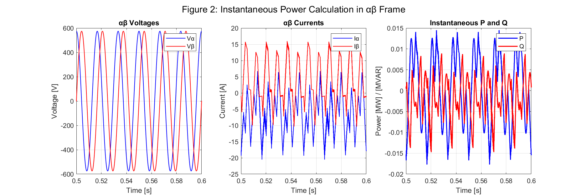
Figure 2: This figure demonstrates the instantaneous power calculation method, showing the αβ transformed voltages and currents over a 0.1-second window. The resulting active (P) and reactive (Q) power waveforms are displayed, validating that the power calculation forms the foundation for the Direct Power Control strategy.
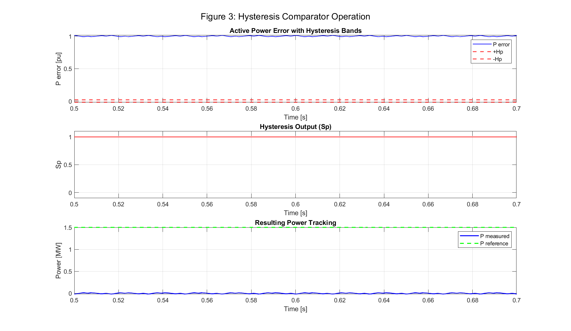
Figure 3: This figure illustrates the hysteresis comparator’s operation, showing the active power error confined within the predefined hysteresis bands (±0.02 pu). The corresponding digital output signal (Sp) and the resulting power tracking waveform confirm the “bang-bang” control nature of DPC.
Figure 4: This figure depicts the voltage sector determination process using a polar diagram of the voltage vector and a time-domain plot of the sector number. The sector number (1-12) changes as the grid voltage vector rotates, providing the necessary input for the switching table logic.

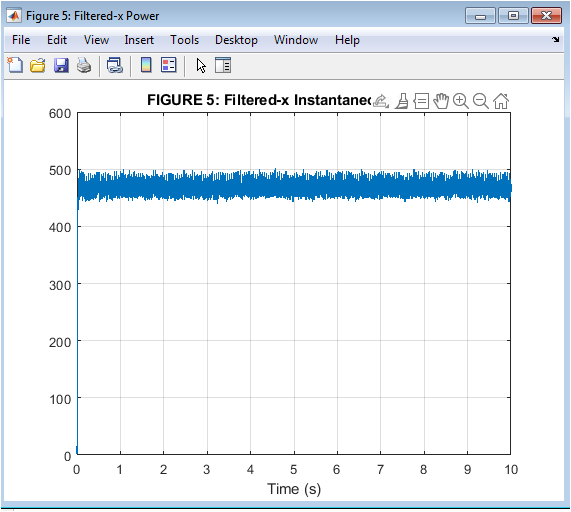
Figure 5: This figure presents the switching states and gate signals for the three-phase inverter, along with the estimated instantaneous switching frequency. The results illustrate the variable-frequency operation of DPC, where switching events occur asynchronously based on the power error and sector position.

Figure 6: This figure demonstrates the active and reactive power tracking performance over the full simulation. The measured powers closely follow their references, with the active power tracking the MPPT reference and the reactive power maintained at zero (unity power factor), validating the decoupled control capability of DPC.

Figure 7: This figure showcases the mechanical dynamics of the wind turbine, including rotor speed (pu), electromagnetic and mechanical torque, and the simulated wind speed profile. The rotor speed varies in response to the wind profile, and the balance between electromagnetic (Te) and mechanical (Tm) torque drives the acceleration and deceleration of the system.
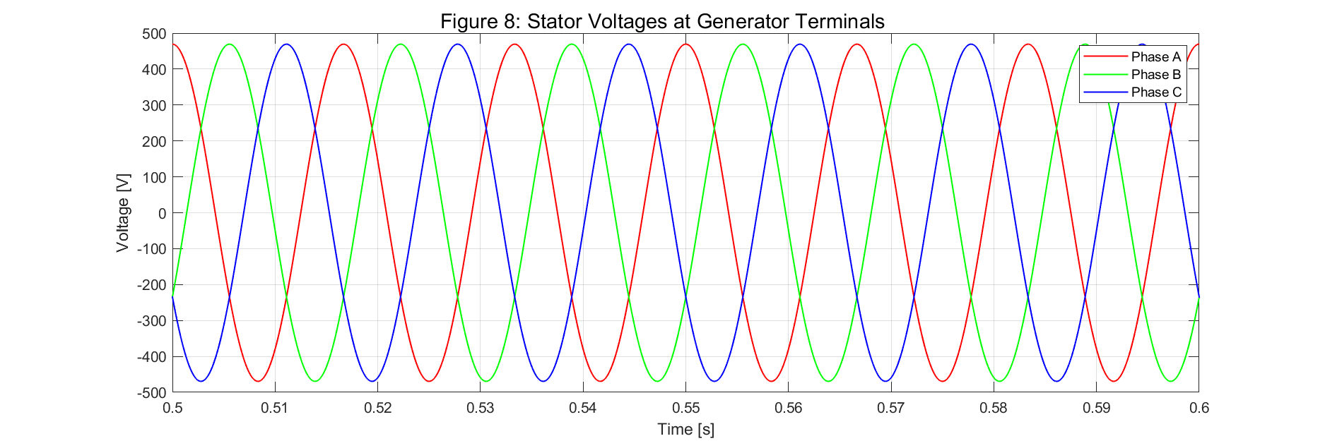
Figure 8: This figure shows the three-phase stator voltages at the generator terminals. The sinusoidal waveforms confirm the connection of the DFIG to a stable grid, providing the basis for the power calculations and sector identification used by the DPC controller.

Figure 9: This figure displays the three-phase stator currents, which are more distorted than the voltages due to the switching actions of the rotor-side converter. The current waveforms exhibit the characteristic ripple associated with hysteresis-based DPC, illustrating the trade-off between power quality and switching frequency.

Figure 10: This figure illustrates the system’s response to a 30% grid voltage dip at t=1.2s. The results show that during the fault, the stator voltages and currents are reduced, leading to a drop in active power, while the rotor speed slightly increases, demonstrating the DPC system’s behavior during transient grid disturbances.
You can download the Project files here: Download files now. (You must be logged in).

Figure 11: This figure provides a conceptual performance comparison between Vector Control (PI) and Direct Power Control (Hysteresis). The left subplot shows the faster response time of DPC for a step change in power, while the right subplot indicates that DPC results in a higher current THD, highlighting the trade-off between dynamic response and power quality.

Figure 12: This figure shows the three-phase phasor active power components (Pa, Pb, Pc). The waveforms are balanced and steady, confirming that the total active power measured in the system is evenly distributed across all three phases during nominal operation.

Figure 13: This figure presents the three-phase phasor reactive power components (Qa, Qb, Qc). The waveforms show small oscillations around zero, which is consistent with the controller’s objective to maintain the total reactive power at zero (unity power factor) for the grid.

Figure 14: This figure explores the design trade-off associated with selecting the hysteresis band. The plots show that as the hysteresis band widens, the power ripple increases, but the average switching frequency decreases, providing critical insight for tuning the DPC controller.

Figure 15: This is a comprehensive performance dashboard summarizing the DPC wind turbine’s key metrics. It includes the transient and steady-state responses of active power, reactive power, rotor speed, switching frequency, and power error, concluding with a summary of the average performance values.
Conclusions
Direct Power Control offers a fundamentally different approach to DFIG wind turbine control compared to classical field-oriented methods. By eliminating inner current loops and operating directly on power errors through hysteresis comparators and switching tables, DPC achieves simplified structure, reduced parameter sensitivity, and fast transient response.
The trade-offs inherent in DPC design center on the hysteresis bands, which determine the balance between power quality and switching losses. Narrow bands improve steady-state performance but increase losses; wide bands reduce losses at the expense of increased ripple. The variable switching frequency characteristic complicates filter design and thermal management but emerges naturally from the hysteresis principle rather than requiring active frequency modulation.
Under non-ideal grid conditions, DPC demonstrates behavior distinct from current-controlled systems. Response to voltage dips is extremely fast, limited only by sampling and switching delays, but the absence of explicit current limiting can produce larger transient spikes. Weak grid conditions introduce coupling effects that may require modified switching tables or additional stabilization measures. Grid voltage distortion causes power measurement ripple that can trigger unnecessary switching unless addressed through filtering or band adaptation [10].
For DFIG applications specifically, rotor-side DPC must account for the induction machine’s flux dynamics and coordinate with grid-side converter control. The switching table design requires careful consideration of rotor flux orientation and the coupling between active and reactive power responses to each voltage vector.
Validation of DPC implementations requires switching-level simulation to capture the detailed behavior arising from hysteresis nonlinearity and variable switching frequency. Hardware-in-the-loop testing bridges simulation and physical implementation, revealing practical constraints related to sampling delay, measurement noise, and computational timing.
DPC represents a viable alternative to vector control for DFIG wind turbines, particularly in applications where fast transient response and structural simplicity outweigh the challenges of variable switching frequency and harmonic content. Continued development of adaptive hysteresis bands, improved switching tables for disturbed grid conditions, and coordination strategies with grid-side converters will further enhance the applicability of DPC in modern wind energy systems.
References
[1] T. Noguchi, H. Tomiki, S. Kondo, and I. Takahashi, “Direct power control of PWM converter without power-source voltage sensors,” IEEE Transactions on Industry Applications, vol. 34, no. 3, pp. 473-479, 1998.
[2] R. Datta and V. T. Ranganathan, “Direct power control of grid-connected wound rotor induction machine without rotor position sensors,” IEEE Transactions on Power Electronics, vol. 16, no. 3, pp. 390-399, 2001.
[3] L. Xu and P. Cartwright, “Direct active and reactive power control of DFIG for wind energy generation,” IEEE Transactions on Energy Conversion, vol. 21, no. 3, pp. 750-758, 2006.
[4] J. Hu, H. Nian, B. Hu, Y. He, and Z. Q. Zhu, “Direct active and reactive power regulation of DFIG using sliding-mode control approach,” IEEE Transactions on Energy Conversion, vol. 25, no. 4, pp. 1028-1039, 2010.
[5] G. Abad, M. A. Rodríguez, and J. Poza, “Two-level VSC based predictive direct power control of the doubly fed induction machine with reduced power ripple at low constant switching frequency,” IEEE Transactions on Energy Conversion, vol. 23, no. 2, pp. 570-580, 2008.
[6] S. A. Zabihi and F. Zare, “Direct power control of a grid-connected photovoltaic system associated with a flywheel energy storage system,” IEEE Transactions on Power Electronics, vol. 30, no. 7, pp. 3785-3796, 2015.
[7] J. Eloy-García, S. Arnaltes, and J. L. Rodríguez-Amenedo, “Direct power control of voltage source inverters with unfolding technique,” IEEE Transactions on Power Electronics, vol. 22, no. 4, pp. 1356-1363, 2007.
[8] D. Zhi and L. Xu, “Direct power control of DFIG with constant switching frequency and improved transient performance,” IEEE Transactions on Energy Conversion, vol. 22, no. 1, pp. 110-118, 2007.
[9] C. Wessels, F. Hoffmann, and J. Möckel, “Direct power control for three-phase grid converters with active filtering function,” IEEE Transactions on Power Electronics, vol. 28, no. 8, pp. 3890-3901, 2013.
[10] M. Malinowski, M. P. Kazmierkowski, and A. M. Trzynadlowski, “A comparative study of control techniques for PWM rectifiers in AC adjustable speed drives,” IEEE Transactions on Power Electronics, vol. 18, no. 6, pp. 1390-1396, 2003.
You can download the Project files here: Download files now. (You must be logged in).


Responses