

Design and Simulation of Sequential Control System for AGV Barrier Mechanism in a Manufacturing Plant
Abstract
This report presents a comprehensive design of a sequential control system for managing pedestrian safety barriers in a manufacturing plant using an Automated Guided Vehicle (AGV) detection system. The solution utilizes a Mealy model, synchronous and asynchronous sequential circuit design methods with JK flip-flops, and includes direction signaling for AGVs moving in both directions. The system is simulated using Proteus for validation and effectiveness. Assumptions in the Mealy model are analyzed, and the impact of incorporating directional indicators in asynchronous logic is discussed. The final design ensures safety, simplicity, and responsiveness in real-time applications.
- Introduction
Automated Guided Vehicles (AGVs) are widely used in modern manufacturing facilities for material handling. As they traverse pedestrian walkways, it becomes crucial to control safety barriers based on the presence of AGVs to prevent accidents. This project focuses on developing a reliable and minimalistic control system using digital design principles. The goal is to detect AGV presence via two sensors, S1 and S2, and to control the barriers using a logic circuit that includes outputs Z (barrier control), ZL (left-to-right direction), and ZR (right-to-left direction) [1].
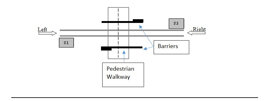
Two sensors, S1 and S2 are used to identify the presence of an automated guided vehicle (AGV) which moves materials around a manufacturing plant as part of a manufacturing process. The system controls the safety barriers across a pedestrian walkway as shown below [2]:
There are also two telemetry signals to the AGV to signal that the barriers are down. One signal for an AGV moving left to right (ZL) and one for an AGV moving in the opposite direction (ZR).
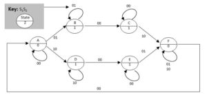
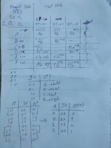
The following Mealy model is used to describe a sequential control scheme for the barriers, based upon a logic high signal to close the barriers, Z, and to indicate the presence of the AGV from the proximity sensors, S1 and S2.
The design is implemented using both synchronous (clocked) and asynchronous (unclocked) digital logic methods. JK flip-flops are used for state memory in the synchronous circuit, and a simplified design using combinational logic is employed for the asynchronous version. The system’s logic is derived from a Mealy machine model and validated through Proteus simulation.
2. Problem Statement
Two sensors, S1 and S2, detect the presence and direction of the AGV. Based on their outputs, the system controls pedestrian barriers (Z) and signals the AGV via ZL and ZR. A robust sequential system is needed that reacts appropriately to sensor input changes, ensures pedestrian safety, and provides directional signals to the AGV.
- Objectives
- Analyze the Mealy model describing AGV barrier logic.
- Design a minimal synchronous circuit using JK flip-flops with Z, ZL, and ZR outputs.
- Simulate the synchronous system in Proteus.
- Design a minimal asynchronous version of the same system with only Z output.
- Compare the design methodologies and evaluate the addition of ZL and ZR in asynchronous circuits.
You can download the Project files here: Download files now. (You must be logged in).
3. Assumptions in Mealy Model
The Mealy model uses the sensors S1 (left) and S2 (right) to detect AGV presence. The following assumptions are made [3]:
- State A (S1=0, S2=0): No AGV detected, barriers open (Z=0).
- A to B (S1=0, S2=1): AGV entering from right, barriers close (Z=1).
- B to C (S1=0, S2=0): AGV passed, barriers open (Z=0).
- C to F (S1=1, S2=0): AGV entering from left, barriers close (Z=1).
- C to A (S1=0, S2=0): Return to idle.
- A to D (S1=1, S2=0): AGV detected from left, barriers close (Z=1).
- D to E (S1=0, S2=0): AGV passed, barriers open.
- E to F (S1=0, S2=1): AGV returning from right.
- F state: Any AGV presence keeps barriers closed.

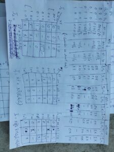
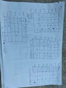
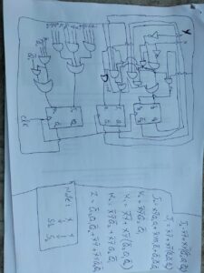
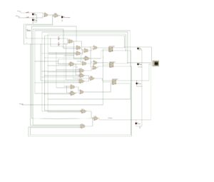
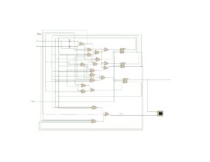
4. Synchronous Circuit Design Using JK Flip-Flops
Using the Mealy model, a minimal number of states are defined. A state transition table is created and minimized using Karnaugh Maps. Each state is encoded and the JK flip-flop inputs are derived using excitation tables. The outputs Z, ZL, and ZR are generated based on the current state and input sensors [4] [5].
- ZL = 1 when AGV moves from left to right (S1=1 then S2=1).
- ZR = 1 when AGV moves from right to left (S2=1 then S1=1).
The synchronous design ensures predictable transitions using a clock pulse and uses edge-triggered flip-flops for reliable operation.
You can download the Project files here: Download files now. (You must be logged in).
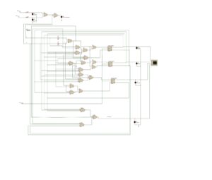
5. Proteus Simulation of Synchronous Circuit
A complete simulation of the JK-based synchronous circuit is developed in Proteus. Flip-flops are wired to represent states, and sensors are implemented with push buttons. LED indicators are used for Z, ZL, and ZR outputs. The simulation demonstrates proper AGV detection and barrier control according to the state transitions described [6] [7].
6. Asynchronous Circuit Design
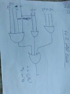
For the asynchronous circuit, no clock signal is used. Instead, the sensor inputs directly drive the circuit outputs through logic gates. The output Z is determined by the current sensor states.
- If (S1=1 or S2=1), then Z=1 (barriers close).
- If (S1=0 and S2=0), then Z=0 (barriers open).
The asynchronous circuit is implemented using basic gates (AND, OR, NOT) and reduces complexity but may be more sensitive to glitches or transient states.
Asynchronous sequential circuits are digital sequential circuits in which the feedback to the input for next output generation is not governed by clock signals. In our designed circuit the circuit output is linked with the input of the S1 and S2 proximity sensors. When any of the proximity sensors will be ON state then the barriers of the AVG will be closed for the pedestrians [8].
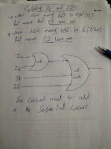
7. Comments on Including ZL and ZR in Asynchronous Design
To incorporate ZL and ZR in the asynchronous design, additional logic gates are required to track the direction of AGV movement. For example:
- ZL = 1 when S1 activates before S2.
- ZR = 1 when S2 activates before S1.
If asynchronous design also be added with the Left and right indicator then OR gate will be added with the S1, S2 and left/right indicator. When any of the left/right indicator, S1 and S2 will be ON. Then the barriers will be closed for the pedestrians and automatic guided vehicle can pass easily. In this case the output will be depended on the S1, S2, ZL and ZR sensors [9].
This requires memory elements or pulse detectors to track the order of activation, making the design more complex and closer to a synchronous system. Thus, for accurate direction tracking, a synchronous design is preferred.
You can download the Project files here: Download files now. (You must be logged in).
8. Conclusion
This report presents a structured solution to a safety-critical problem in AGV-based manufacturing systems. The Mealy model forms the basis for both synchronous and asynchronous circuit designs. The synchronous circuit using JK flip-flops proves to be robust and capable of handling complex scenarios including directional signaling [10]. The asynchronous circuit is simpler and useful for applications where only basic control (barriers open/close) is needed. The Proteus simulation validates the correct operation of the synchronous system. Overall, synchronous designs are better suited for complex behavior and safer operations, while asynchronous designs can serve as quick, resource-efficient solutions for simpler needs.
- References
- Mano, M. M., & Ciletti, M. D. (2017). Digital Design With an Introduction to the Verilog HDL. Pearson.
- Wakerly, J. F. (2005). Digital Design: Principles and Practices. Pearson Education.
- Floyd, T. L. (2013). Digital Fundamentals. Pearson.
- Roth, C. H. (2016). Fundamentals of Logic Design. Cengage Learning.
- Proteus Design Suite. (2024). Labcenter Electronics. [https://www.labcenter.com/]
- Hamacher, V. C., Vranesic, Z. G., & Zaky, S. G. (2012). Computer Organization and Embedded Systems. McGraw-Hill.
- Roth, C. H., & Kinney, L. L. (2013). Digital Systems Design Using VHDL. Cengage Learning.
- Brown, S., & Vranesic, Z. (2009). Fundamentals of Digital Logic with VHDL Design. McGraw-Hill.
- Cormen, T. H., et al. (2009). Introduction to Algorithms. MIT Press.
- IEEE Std 1474.1-2004, Standard for Communications-Based Train Control Performance Requirements, IEEE, 2004.
You can download the Project files here: Download files now. (You must be logged in).
Keywords: Digital Logic Gates, Sequential Circuit, Mealy model, JK Flip flops, Control System, Automated Guided Vehicle (AGV), Manufacturing Plant


Responses