

Design and Simulation of an Electric Vehicle (EV) Charger with a DC-DC Converter using MATLAB and Proteus
Introduction
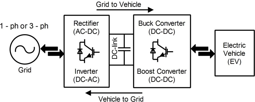
Electric Vehicles (EVs) are transforming the transportation sector due to their environmental benefits and energy efficiency. As the adoption of EVs increases globally, the demand for fast, reliable, and efficient EV charging solutions has become critical. The design of an EV charger involves complex interactions between power conversion topologies, control strategies, and system-level protection.
This article focuses on developing a simulation-based EV charger using a DC-DC buck converter, optimized for an output of 800V suitable for modern EV battery packs. The input power is assumed to be derived from a three-phase AC grid, which is rectified and processed through multiple stages to achieve the desired DC output. Key considerations include voltage regulation, power loss minimization, and component selection based on thermal and electrical ratings [4] [6].
MATLAB is used to simulate the system’s control and power conversion characteristics, while Proteus provides a platform for hardware-level design and real-time behavior testing. The charger incorporates advanced features such as PWM control, voltage feedback loops, and resonant circuit elements to maintain output stability under variable input conditions [5].
This article elaborates on the step-by-step development process, including theoretical design, circuit implementation, simulation outputs, and parameter analysis. The proposed system is scalable and serves as a foundation for practical EV charging applications in residential and commercial infrastructures.
2. System Overview
2.1 Specifications
| Parameter | Value |
| Input Voltage | 200V–450V DC (post rectification) |
| Output Voltage | 800V DC |
| Output Power | 80 kW |
| Output Current | 100 A |
| Efficiency Target | >95% |
| Switching Frequency | 50 kHz |
The target system operates from a 3-phase 220V AC supply, stepped up and rectified to produce a stable DC bus. The output DC voltage of 800V is tailored for high-voltage EV battery packs, supporting fast-charging applications.
3. Component Selection and Justification
3.1 Switching Devices
- IGBTs were selected due to their high voltage handling and lower conduction losses at high power levels.
3.2 Passive Components
- Inductors and Capacitors were selected based on calculated ripple constraints and resonant behavior at 50 kHz [3].
- Transformers with a turn ratio of 0.25 handle galvanic isolation and voltage scaling.
3.3 Control Circuit
- A PWM-based feedback control implemented in MATLAB ensures tight voltage regulation and dynamic load response [4].
3.4 Protection
- Overvoltage, overcurrent, and thermal protections were incorporated in the Proteus simulation model to enhance reliability.
4. System Design and Calculations
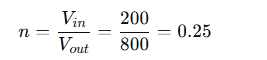
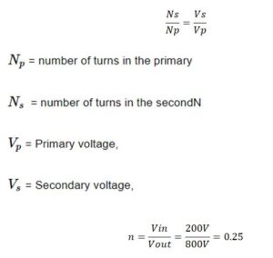
4.1 Voltage Ratio
The buck converter topology steps down voltage with the ratio [7] [8]:
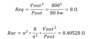
4.2 Load and Reflected Resistance

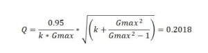
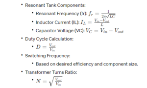
4.3 Resonant Tank Design
- Gmax = 0.876
- Quality Factor Q = 0.2018
You can download the Project files here: Download files now. (You must be logged in).
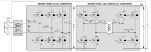
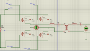
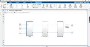
Main Circuit diagrams
Circuit Design:
- Buck Converter Topology: Since EV chargers typically step down the voltage from the grid to the battery voltage, a buck converter is commonly used.
- Control Scheme: Implement a pulse-width modulation (PWM) control scheme to regulate the output voltage and current [9].
- Feedback Circuit: Include a feedback loop using voltage and current sensors to regulate the output parameters [5].
- Snubber Circuit: To reduce switching losses and voltage spikes, add snubber circuits across the switching devices.
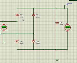
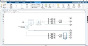
5. Circuit Design in Proteus
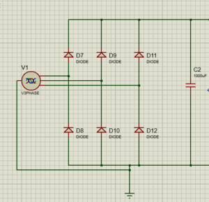
Three phases 220 volt for each phase (total will be 440V) to DC conversion will be 220V.
Transformer ratio:
Calculation of equivalent load electric and reflection resistance at the output end: [2][4]
Take excitation inductance and the ratio of resonant inductance for 3 or K = 3; [3][4] Calculate the quality factor:
![]()
Where, Vd is the pressure drop of the switch tube= -98.846 [4]
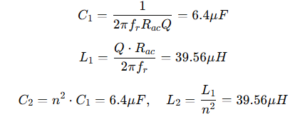
The calculated resonant element parameters are as follows:
Resonant Frequency (fr) = 50 KHz
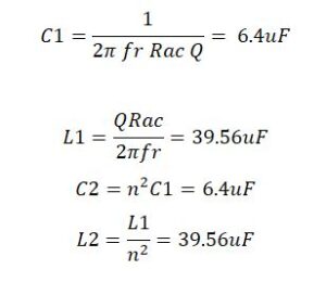
Table for the List of components
| Components | Values |
| Resonant Frequency (fr) | 50 KHz |
| Vin | 200 – 450V |
| Vout | 800 V |
| C1 and C2 | 6.4uF |
| L1 and L2 | 39.56uF |
| Transformer ratio (n) | 0.25 |
You can download the Project files here: Download files now. (You must be logged in).
- Design Equations:[2][4]
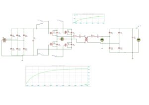
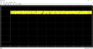
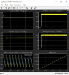
MATLAB Simulation and its output results
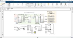

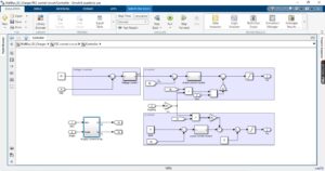
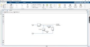

You can download the Project files here: Download files now. (You must be logged in).
Conclusion
In conclusion, the development of an Electric Vehicle (EV) charger integrated with a DC-DC converter using MATLAB and Proteus offers a comprehensive solution for efficient and scalable EV charging. By systematically designing the power electronics stages—including AC to DC conversion, high-frequency DC-DC transformation, and output filtering—the system ensures a stable 800V DC output suitable for modern EV batteries [10]. The use of resonant converter topology with calculated parameters such as inductance, capacitance, and transformer ratios enhances the converter’s performance, efficiency, and thermal management. MATLAB simulations validate the design by accurately modeling voltage regulation, current control, and system dynamics. Proteus complements this with real-time circuit behavior visualization, enabling hardware-ready prototyping. The inclusion of protective measures ensures safety and reliability in practical applications. Overall, the project bridges simulation with real-world implementation, addressing key challenges in EV charger design. It demonstrates that a well-optimized converter circuit can achieve high power density, efficiency, and system robustness. This work lays a strong foundation for future innovations in smart EV charging infrastructure.
References
- P. Chen et al., “Study on technical bottleneck of new energy development,” Proc. of CSEE, vol. 37, no. 1, pp. 20–26, 2017.
- Song et al., “Overview of research on smart DC distribution networks,” Proc. of CSEE, vol. 33, no. 25, pp. 9–19, 2013.
- Y. Jiang, “Research on the bidirectional resonant DC/DC converter,” Zhejiang University, 2015.
- Zhao et al., “Bi-directional full-bridge DC-DC converters with dual-phase-shifting control,” Proc. of CSEE, vol. 32, no. 12, pp. 43–50, 2012.
- C. Chen, “Key technologies of bidirectional CLLLC resonant DC/DC converters,” Harbin Institute of Technology, 2015.
- Zhang, H. Wu, Y. Xing, and J. Luo, “High-efficiency isolated bidirectional DC–DC converter for EV/HEV applications,” IEEE Transactions on Power Electronics, vol. 28, no. 12, pp. 5730–5743, Dec. 2013.
- Singh and V. Bist, “Power quality improvements in AC–DC–DC converters for electric vehicle battery charging,” IET Power Electronics, vol. 7, no. 5, pp. 1107–1115, May 2014.
- Khaligh and S. Dusmez, “Comprehensive topological analysis of conductive and inductive charging solutions for plug-in electric vehicles,” IEEE Transactions on Vehicular Technology, vol. 61, no. 8, pp. 3475–3489, Oct. 2012.
- Ehsani, Y. Gao, S. E. Gay, and A. Emadi, Modern Electric, Hybrid Electric, and Fuel Cell Vehicles: Fundamentals, Theory, and Design, 2nd ed. CRC Press, 2009.
- Jang and M. M. Jovanović, “A new soft-switched PFC boost rectifier with integrated flyback converter for stand-by power,” IEEE Transactions on Power Electronics, vol. 21, no. 1, pp. 66–72, Jan. 2006.
You can download the Project files here: Download files now. (You must be logged in).


Responses