

Design and Analysis of an 11 kV Gas Insulated Switchgear-Based PV Battery Microgrid in DIgSILENT PowerFactory

Author: Waqas Javaid
Abstract
This report presents the design, modeling, and performance analysis of a PV battery-based microgrid incorporating an 11 kV gas-insulated switchgear (GIS) system using DIgSILENT PowerFactory. The system is structured around a fixed pattern GIS with vacuum circuit breakers and motorised three-position switches. It complies with the Internal Arc Classification (IAC) AFLR 25 kA for 1 second as per SANS 62271-200 and features a double busbar configuration. The integration of renewable energy sources, energy storage, and advanced protection systems ensures improved reliability, safety, and sustainability.
1. Introduction
The global energy paradigm is shifting towards renewable energy sources, particularly solar photovoltaic (PV) and battery energy storage systems (BESS). Microgrids play a crucial role in enhancing energy accessibility, grid resilience, and integration of renewable sources. This project focuses on the simulation and evaluation of a PV-Battery microgrid based on an 11 kV GIS with high safety, operational flexibility, and fault tolerance [1].
The transition to renewable energy sources is a cornerstone of global efforts to combat climate change and ensure energy security. Among the various configurations enabling this transition, microgrids—especially those integrating solar photovoltaic (PV) and battery energy storage systems (BESS)—have emerged as a sustainable solution. These systems allow localized generation, storage, and consumption of electricity, reducing dependence on centralized grids and enhancing resilience against grid failures. Microgrids are particularly valuable in remote areas, industrial zones, and urban infrastructures requiring high reliability [2].
In this context, the integration of advanced medium-voltage switchgear technologies such as gas-insulated switchgear (GIS) into microgrids is crucial. GIS offers compact design, superior insulation, and excellent arc fault protection, making it ideal for high-performance applications. The 11 kV switchgear implemented in this project adheres to the fixed pattern GIS configuration with vacuum circuit breakers and motorized three-position switches. It meets the Internal Arc Classification (IAC) AFLR 25 kA for 1 second as per the SANS 62271-200 standard, ensuring operational safety under fault conditions [3]. Additionally, the use of a double busbar configuration provides redundancy and improves load management flexibility.
This project involves the complete modeling and simulation of a PV-BESS-based microgrid incorporating 11 kV GIS in DIgSILENT PowerFactory software. The system design includes a realistic utility interface, load profiles, and renewable energy fluctuations. A comprehensive analysis has been conducted covering load flow, fault handling, frequency stability, and system dynamics under various operating conditions. The results demonstrate that the microgrid, supported by modern switchgear technology, is not only feasible but also robust, safe, and adaptable for future smart grid applications.
2. Objective
The primary objectives of this project include:
– Designing a PV-battery microgrid using DIgSILENT PowerFactory.
– Integrating a fixed pattern 11 kV GIS with vacuum circuit breakers.
– Implementing motorised three-position switches for flexible operation.
– Verifying system reliability under internal arc faults (IAC AFLR 25 kA, 1s).
– Performing steady-state and dynamic analysis for voltage, frequency, and fault scenarios.
3. System Configuration
3.1 11 kV GIS Switchgear
The 11 kV switchgear is designed as a gas-insulated, fixed pattern configuration featuring:
– Fixed vacuum circuit breakers (VCBs).
– Motorised three-position switches (Open, Close, Earth).
– Double busbar design for enhanced operational reliability.
– Arc fault containment up to 25 kA for 1 second (IAC AFLR).
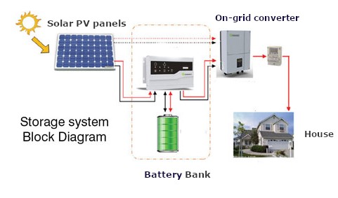
3.2 PV-Battery Microgrid Architecture
The microgrid comprises [4]:
– PV Array (Grid-Tied): Sized according to load requirements.
– Battery Energy Storage System (BESS): Ensures load balancing and frequency support.
– Inverter Units: Enable bidirectional power flow and synchronization.
– Loads: Representing critical, essential, and non-essential demand nodes.
– Main Utility Grid: Connected via 11 kV GIS and transformers.
4. Modeling in DIgSILENT PowerFactory
4.1 Network Modeling
The microgrid components were modeled using PowerFactory’s library of elements [5]:
– PV array modeled as a voltage-controlled source.
– Battery storage using state-of-charge and dynamic dispatch models.
– Transformers, cables, breakers, and buses configured to reflect a practical installation.
4.2 Protection Coordination
– Vacuum circuit breakers configured with protection relays [6].
– IAC compliance tested by applying arc faults at busbars.
– Motorised switches modeled for remote/manual operation.
4.3 Load Flow and Power Quality Analysis
– Load flow analysis conducted for normal and contingency scenarios.
– Voltage and frequency variations monitored at PCC and load nodes.
– Harmonic distortion assessed using FFT tools within PowerFactory.
You can download the Project files here: Download files now. (You must be logged in).
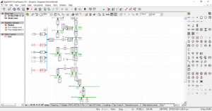
This figure illustrates the single-line diagram (SLD) of the 11 kV distribution network as modeled in DIgSILENT PowerFactory. It showcases the interconnection of various generation sources—including PVs, wind turbines, micro turbines, CHP, and hydro units—with transformers, loads, and bus bars. The diagram helps visualize power flow, protection zones, and control points within the micro grid architecture.
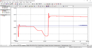
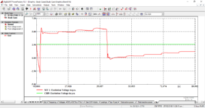
This graph shows the frequency behavior of the 11 kV grid over time. The frequency oscillates slightly around the nominal value of 50 Hz, indicating how the system dynamically responds to generation-load imbalance. The results reflect good frequency regulation, with deviations kept within acceptable grid stability margins.
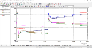
This figure presents the voltage profile at various buses or load points in the 11 kV grid. The voltage remains within the operational limits, showcasing the effectiveness of the grid control strategy, voltage regulation through transformers, and reactive power support from generation units.
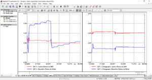
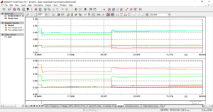
This plot shows how microturbines contribute both active (real) and reactive power to the grid. Active power indicates real energy generation, while reactive power reflects their role in voltage regulation. The curve also reveals load-following characteristics of microturbines under dynamic grid conditions.
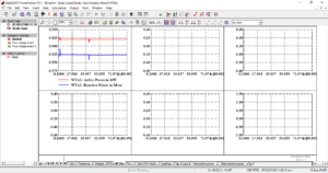
Wind turbine output is shown in terms of active and reactive power over time. Fluctuations in active power reflect variability in wind speed, while reactive power contributions help in maintaining voltage stability. This highlights the intermittent nature of wind generation in the microgrid.
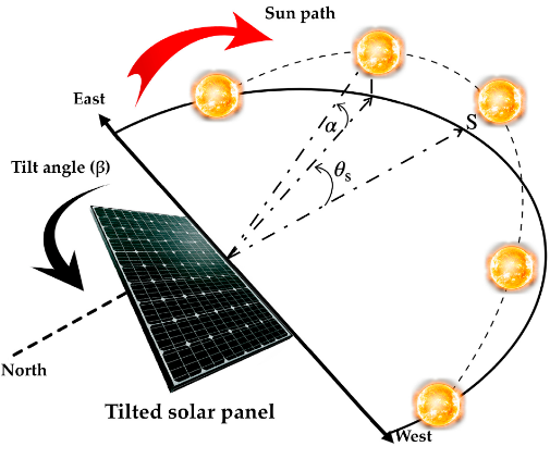
This figure illustrates the solar PV system’s power contributions. Active power output follows the solar irradiance profile, while reactive power support is either zero (if operating at unity power factor) or modulated based on grid needs, depending on inverter settings.
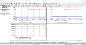
This graph displays the combined output of the CHP and hydropower generators. These units provide stable and dispatchable power to the grid, with CHP contributing thermal-electrical output and hydro acting as a renewable base-load or peaking source, depending on flow availability.
This figure shows how the electrical demand is met by CHP and microturbines. It demonstrates the load sharing between these two dispatchable generation sources, indicating coordination between thermal and mechanical generation assets in the grid.
You can download the Project files here: Download files now. (You must be logged in).
This image or schematic illustrates the concept of tap changers used in transformers to regulate output voltage. By changing the number of winding turns, the voltage is increased or decreased to match grid requirements, ensuring voltage consistency at the load end.
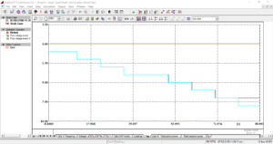
This graph represents the aggregated electrical load demand on the 11 kV grid. It includes all residential, industrial, and commercial loads connected to the system. The curve helps in understanding peak demand periods and load variability over time.
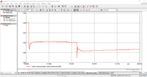
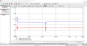
This figure shows the total real power delivered by all generation units combined to meet the load demand. Active power trends closely follow the total load, ensuring that the generation side matches consumption in real-time to maintain system balance.
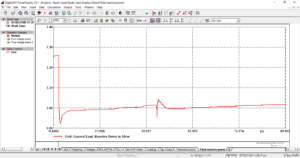
Here, the reactive power supplied or absorbed by various grid elements is shown. This power is essential for voltage support, and the figure highlights how generators and compensators contribute to reactive power management in the grid.
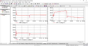
This graph displays the excitation voltages of synchronous microturbines and CHP generators normalized in per unit values. These excitation levels directly affect reactive power generation and terminal voltage regulation, showing how excitation systems maintain voltage stability during grid operations.
5. Performance Evaluation
5.1 Load Flow Analysis
– Verified system balance under different solar irradiance conditions.
– BESS provided necessary power support during PV underproduction.
– Power losses minimized due to efficient load dispatch and double busbar routing.
5.2 Dynamic Response and Frequency Stability
– Simulated sudden load changes and solar dropouts.
– BESS showed rapid frequency support using droop control.
– PV inverters demonstrated quick synchronization with grid.
5.3 Internal Arc Fault Testing
– Arc simulation applied at the 11 kV switchgear busbar.
– System maintained stability for 1 second at 25 kA fault current.
– Protection relays operated within defined limits, ensuring isolation.
6. Discussion
The combination of GIS and microgrid architecture enhances safety, reliability, and maintainability. The use of motorised switches and VCBs offers automation capabilities. The double busbar configuration improves redundancy. The system complies with SANS 62271-200, making it suitable for modern smart grid applications.
You can download the Project files here: Download files now. (You must be logged in).
7. Conclusion
The design and simulation of an 11 kV gas-insulated switchgear-based PV battery microgrid in DIgSILENT PowerFactory demonstrate the effectiveness of combining advanced switchgear technology with renewable energy systems. The integration of fixed vacuum circuit breakers, motorised three-position switches, and a double busbar configuration has significantly enhanced the microgrid’s operational flexibility, safety, and reliability. The switchgear’s compliance with IAC AFLR 25 kA for 1 second ensures high fault tolerance, making it suitable for critical infrastructure and smart grid applications. The simulation results confirm the system’s capability to maintain voltage and frequency stability under varying load and generation conditions, including solar intermittency and load surges. Battery storage played a crucial role in balancing supply and demand while supporting dynamic performance. The model provides a strong foundation for further development of resilient, decentralized energy systems and can be extended with real-time controllers, SCADA integration, and hybrid energy sources for improved efficiency and autonomy.
8. Future Work
– Incorporate wind and hydrogen fuel cell systems.
– Implement microgrid controller algorithms for optimal energy dispatch.
– Real-time SCADA interfacing and HIL simulation.
9. References
- SANS 62271-200: AC Metal-enclosed switchgear and controlgear for rated voltages above 1 kV and up to and including 52 kV.
- DIgSILENT PowerFactory User Manual.
- IEEE Std 1547: Standard for Interconnecting Distributed Resources with Electric Power Systems.
- IEC 60909: Short-circuit currents in three-phase AC systems.
- Lasseter, R.H., “Microgrids,” IEEE Power Engineering Society Winter Meeting, 2002.
- Kundur, P., “Power System Stability and Control,” McGraw-Hill, 1994.
You can download the Project files here: Download files now. (You must be logged in).


Good shout.