

Single-Phase, Bidirectional, 7.7 kW EV charger and Totem Pole On-Board Charging/Discharging Infrastructure
Author: Waqas Javaid
Electronic and Electric Engineering, Bahria University Islamabad
Abstract
In the present scenario of the fossil fuel crisis, a shift from conventional transportation to electric vehicles (EVs) is the goal, and it is necessary to make it economically feasible. Developing an efficient charger with mid-range power level may successfully resolve this problem. In this direction, an EV charging infrastructure has been proposed to achieve grid-to-vehicle (G2V) charging, with vehicle-to-grid (V2G) capability. In G2V mode, the proposed infrastructure consists of an on-board, single-phase, 7.7 kW totem pole converter in continuous conduction mode to achieve high-power fac- tor correction (PFC). Additionally, instead of conventional Si power MOSFET, an SiC-based converter is introduced to lower the switching losses at high switching frequency with smaller filters. Using an SiC-based converter leads to increased efficiency (more than 98%) and reduced total harmonic distortion (less than 5%), making the system economical. Simultaneously, to make the system more economical, the proposed converter works as an inverter to feedback the power to the grid in V2G mode. Furthermore, to analyse the feasibility, the proposed infrastructure has been simulated and its performance is validated using the simpower tool in MATLAB/Simulink and LTSpice environment.
1. Introduction
In the fast-growing, emission-free transportation revolution, the participation of elec- tric vehicles (EVs) has increased exponentially. EVs are rapidly becoming an essential facet in the drive for attaining sustainable energy goals. In this regard, the expansion of the transportation revolution is being carried out by offering a versatile choice of EV chargers and charging infrastructures for end users. The choices of the EV charging infrastructures are classified based on the power levels, such as level 1, level 2, and level 3 [1,2]. Amongst all levels, level-2 is best suited to single-phase and mid-range power applications. On the other hand, the charging infrastructure is constructed in terms of component placement, such as out-board and in-board placement—known as off-board and on-board, respec- tively [3]. Among both infrastructures, off-board charging has an advantage over on-board charging in terms of weight, space, and cost constraints. However, off-board chargers have the risk of vandalism and added clutter in an urban environment, as identified by Lacroix et al. in [4]. However, the advancement in power electronics made it possible to overcome some problems, such as size, weight, and cost constraints for the on-board charging infrastructure [5]. At the same time, the on-board charging infrastructure has added advantages when it works in bidirectional mode. In a bidirectional charging infras- tructure (BDCI), power flow is from the grid to the battery and vice versa. Additionally, the connected batteries have also been used to support the grid as an energy storage system in load-demand management and reactive power compensation [6,7]. However, the charging and discharging performance depends upon the components used in the on-board BDCI.
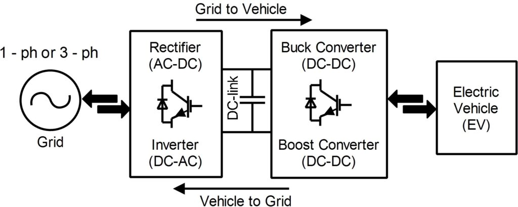
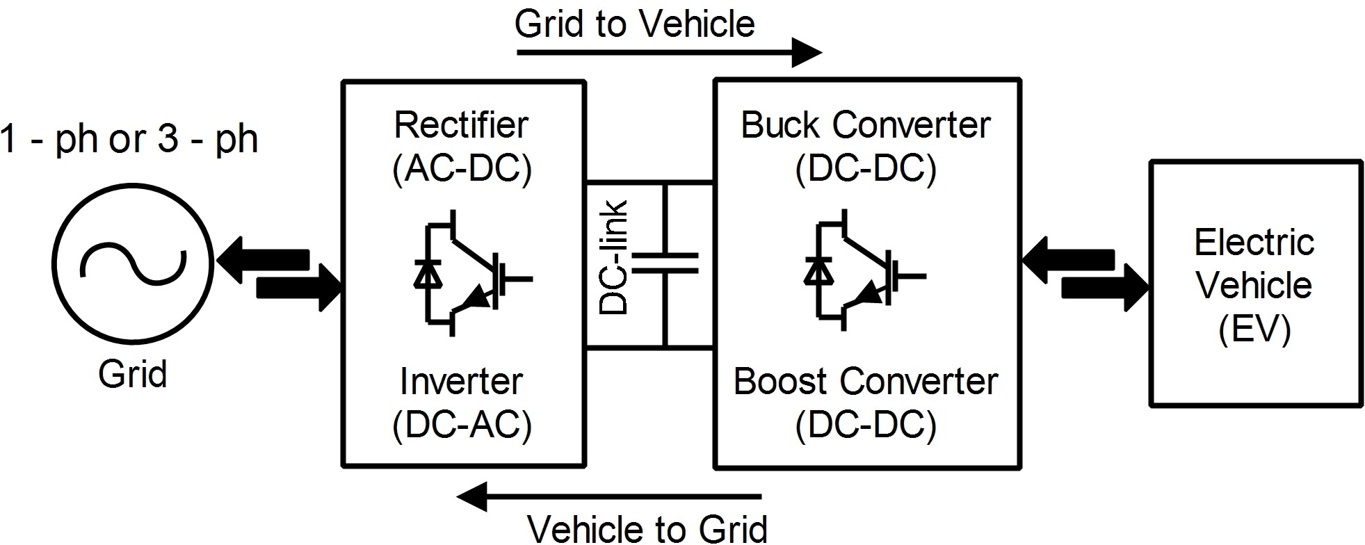
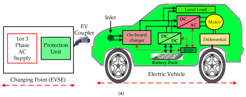
A BDCI consists of the grid, two bidirectional converters, and the EV/EVs. The first bidirectional converter is connected with the grid, which works as a rectifier (AC- DC) and an inverter (DC-AC) in grid-to-vehicle (G2V) and vehicle-to-grid (V2G) mode, respectively. The rectifier is used for the power factor correction (PFC) in G2V mode and the inverter is used to feedback the power from EV to the grid in V2G mode. On the other hand, the second bidirectional DC-DC converter is connected between DC-link of the first bidirectional converter and EV, which works in buck and boost mode, as shown in Figure 1. The buck and boost mode of the bidirectional DC-DC converter always depends upon the voltage level of the EV and DC-link. However, the first bidirectional converter plays a significant role in BDCI, ensuring its size, efficiency, power density, and harmonic content. In this direction, many researchers have proposed their contributions in resolving issues such as size, efficiency, power density, topology, and harmonic content. Skauras et al. [8] represented every aspect of EV’s existence, such as the source of energy types, charging technologies, and emerging issues. In [9], Youn et al. explained that the continuous conduction mode (CCM) eliminates the input current distortion, which is very much required to improve the power factor (PF). With respect to the grid-side converter topology, the authors in [10–13] presented various bridge-less PFC topologies which reduce the overall conduction loss by reducing the number of rectifiers essentially eliminating the diode bridge rectifier that conducts the current from the input to the output. Similarly, in [14–18], the authors presented various topologies of PFC to obtain high efficiency as well as PF. Amongst various topologies, a bridge-less topology, i.e., totem pole, attracted enormous attention from researchers due to low conduction losses, less switching devices, and low common mode electromagnetic interferences (EMI). Authors have achieved an improved efficiency, power density, and power factor with fewer switching components, but are unable to present a bidirectional functionality of the power converter. Therefore, in [19–23], authors proposed a bidirectional approach to achieve the power flow in G2V and V2G modes.
However, the approaches mainly focused on utilizing EV batteries in V2G mode for vehicle-to-home functions, reactive power operation, and distributed energy storage. In [2], Yuan et al. presented a review on the existence of various topologies, future trends, challenges, and technologies used for an on-board BDCI. Similarly, Angshuman et al. [24] and Blaabjerg et al. [25] presented a review on bidirectional power converters. Amongst various bidirectional PFC topologies, the full-bridge topology is the most common due to its simple structure and control flexibility, achieving unity PF operation easily. However, harmonic distortion of the current waveform can be a major concern, and alternate control methods need to be identified to answer this problem. Moreover, the full-bridge bidi- rectional converter requires bus capacitor of higher capacitance to act as an intermediate energy storage element, which increases the cost and footprint of the system and reduces its reliability and power density capability. Therefore, to improve the reliability and power density capability, and reduce the size of bus capacitor, researchers have emphasized on using wideband gap (WBG) devices [26,27]. In [28–30], authors reported that the GaN and SiC WBG devices have better figure-of-merit, significantly better reverse recovery property, and lower switching losses as compared with the conventional Si MOSFETS. In this respect, Li et al. [31] have presented an on-board BDCI, which includes SiC-based WBG for AC-DC operation, and GaN-based WBG for DC-DC operation. However, authors have performed critical conduction mode (CRM) or boundary mode operation to realize zero-voltage switching. In CRM operation, it is controlled to stay at the boundary condi- tion. In CRM, constant on-time control is used to change line voltage across the line cycle. Simultaneously, the reset time for the input inductor varies and the operating frequency changes accordingly, in order to maintain the boundary mode operation to minimize the peak input inductor current. However, the proposed strategy imposes an extra burden of power electronics switches and control complexity. Since the CCM operation is a require- ment of the high-power application, its use with WBG devices (GaN and SiC) resolves the issue of reverse recovery. Wang et al. [32] and Tang et al. [33] introduced SiC-based power converters, which offer low output capacitance, high voltage blocking capability, extended soft-switching range, high power density capability, low reverse recovery charge, and better thermal characteristics. Similarly, Chen et al. [34] introduced an SiC-MOSFET-based, bidirectional on-board EV charger. In this article, authors have used SiC MOSFET due to the high threshold voltage, and improved turn ON and OFF times as compared with GaN WBG devices. Additionally, GaN WBG devices are limited for the low-power applications. Therefore, for the high power application SiC-based WBG devices are used for the higher efficiency. However, the use of SiC WBG devices increases efficiency significantly but fails to improve the power density. Thus, to improve the power density level of the system, the switching frequency must be increased [35]. In [35–41], many researchers have proposed a high switching frequency (from kHz to MHz)-based solution with WBG devices in order to improve the power density level. On this point, Jimmy and Paul [42] have presented an analysis of increment in power density as well as the efficiency concerning the switching frequency. The authors have analysed that the switching frequency can increase at a certain range and after that, the efficiency decreases. Therefore, the optimal switching frequency will always depend on its use, whether it needs high density, efficiency, or both, whereas, in [43], authors have reported a bidirectional totem pole PFC with resonant dual active bridge converter using SiC WBG devices. However, the complexity of the overall system has increased due to resonant dual bridge converter. Similarly, Li et al. [44] have presented an on-board charging infrastructure with SiC WBG devices for bidirectional LLC DC-DC converter. However, PFC operation is performed with an interleaved bridge-less totem pole PFC which adds an extra burden on the overall system.
Based on the studies mentioned earlier, it is evident that the totem pole PFC converter is most suitable for charging EV. With few topology modifications, it is capable of working in bidirectional mode. The use of SiC WBG devices in bidirectional totem pole converter makes it more beneficial due to improved efficiency and power density. Additionally, the combination of WBG devices with totem pole topology enables the use of a converter at high switching frequency, which benefits in reducing the size of EMI filters and lowering the total harmonic distortion (THD) content. Therefore, this paper intends to apply an SiC-based bidirectional totem pole charging infrastructure for EV application in G2V and V2G mode.
The significant contribution of this paper is summarized as follows.
- A CCM-control-based totem pole PFC offers simple structure with higher efficiency in bidirection mode to charge and discharge the EV batteries in G2V and V2G modes,
- Due to the use of SiC device, totem pole converter is capable of operating at the high switching frequency, which reduces the size of the interfacing inductor and achieve higher efficiency as well.
- An optimized switching frequency has been analysed to obtain the high efficiency and power density.
- At an optimized switching frequency, a small sized interfacing inductor achieves lower THD.
Furthermore, the detailed implementation of the BDCI is structured as follows. The design parameters of the BDCI is presented in Section 2. Whereas Section 3 presents the G2V and V2G mode control. The performances of the BDCI is discussed in Section 4 and finally, the conclusions are drawn in Section 5.
2. Brief Detail and Parameter Design
Figure 2 depicts the detailed structure of the BDCI. This type of BDCI is adopted for personal as well as commercial use with the range of 3.3 kW to 11 kW. This system consists of two stages. The first stage includes the grid and a grid-side bidirectional (GSBD) converter. The GSBD converter operates as a rectifier and an inverter in charging and discharging mode, respectively, to maintain the power balance between EV and the grid. On the other hand, the second stage consists of a battery-side bidirectional (BSBD) DC-DC converter connected with the EV batteries. Both stages are interfaced with the DC-link capacitor and operate in charging and discharging mode for G2V and V2G applications. In both charging and discharging modes, the design guideline and sizing of the parameters for the proposed system depend upon the system rating, which is presented in Table 1. Firstly, in the charging mode, the calculation of design parameters for CCM totem pole PFC is presented as follows.
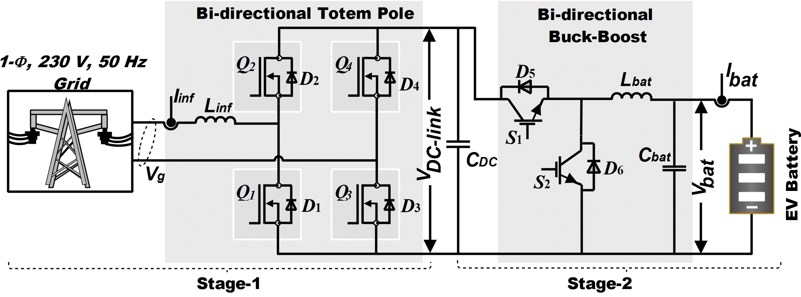
Table 1. System specifications for G2V and V2G mode.
| G2V/Charging Mode | ||
| Vg and fl | 230 V and 50 Hz | |
| Vo or VDC−link | 400 V | |
| Prat | 7.7 kW | |
| fSW | 65 kHz | |
| ∆Iripp | 20% | |
| ∆VDC−link | 5% | |
| η target | >95% | |
| PF target | >98% | |
| V2G/Discharging Mode | ||
| VDC−link | 400 V | |
| Vg and fl | 230 V and 50 Hz | |
| Prat | 7.7 kW | |
| fSW | 65 kHz | |
| THD | <5% |
2.1. Inductor Design
In this proposed BDCI, the grid interfacing inductor (Lin f ) has a major role to play. Lin f will be the common interfacing inductor for both G2V as well as V2G mode. Therefore, its value should withstand the maximum current. Additionally, the Lin f suppresses the current harmonics and acts as a power factor (PF) booster in PFC operation. The value of Lin f is calculated as follows [45]:
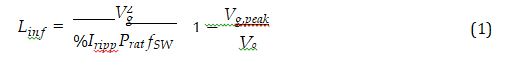
where Vg, Vg,peak, Vo, Iripp, Prat, and fSW are the grid voltage, peak grid voltage, output voltage or DC-link voltage, inductor ripple current, rated power and switching frequency, respectively.
2.2. Output or DC-Link Capacitor Design
Similarly, the output capacitor (CDC) is the main energy-storing element. Simulta- neously, it is, relatively, the most expensive and bulky element of the PFC. Therefore, its sizing should be optimum so it can meet the specifications of the system. Mainly, the value of the output capacitor is determined considering the output current ripple (∆IDC−link), the allowable voltage ripple (∆VDC−link), and the required hold-up time (thold). Among these, ∆IDC−link and ∆VDC−link are considered to calculate the CDC, presented as follows [45,46]:

2.3. Switching Frequency
Additionally, in order to design the Lin f , the switching frequency plays a big role. It impacts on sizing of interfacing inductor which leads to improving the power density. In other means, the higher fSW, the smaller Lin f value and size. However, the improvement in power density impacts efficiency. Therefore, to achieve optimal power density and efficiency, the switching frequency range should be decided. Hence, from (1), the switching frequency is derived as follows [47].

where ω is the angular frequency of the input grid voltage and ωt varies between 0 and π. Therefore, from (5) it is evident that the fSW has a wide range and varies with respect to the input voltage.
2.4. Bidirectional DC-DC Converter Design
Furthermore, in the proposed system, the second stage consists of a battery-side bidirectional (BSBD) DC-DC converter that operates in two modes, i.e., charging and discharging for G2V and V2G applications, respectively. During charging mode, it acts as a buck converter. On the other hand, it acts as a boost converter while discharging.
2.4.1. Charging Mode
In charging mode, DC-link is connected as an input of bidirectional converter and EV batteries are connected as a load on the output side. Hence, to achieve the voltage level of batteries (Vbatt) at the output side, BSBD converter operates in buck mode with components as an inductor (Lbuck) and capacitor (Cbuck). The values of (Lbuck) and (Cbuck) depend upon the corresponding voltage and current rating of the converter. These values are calculated as follows:
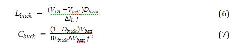
where ∆IL and f are the ripple current and switching frequency for the buck mode, respectively.
2.4.2. Discharging Mode
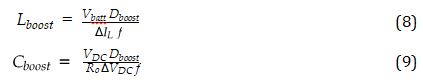
Similarly, in discharging mode, BSBD converter is interfacing the DC-link and the battery. In this mode, the battery acts as an input source and DC-link as the output. The DC- link voltage level is higher than the battery terminal voltage. Therefore, the BSBD converter operates in boost mode with the help of the value of the corresponding components. The components, such as the inductor (Lboost) and capacitor (Cboost) values in boost mode, are calculated as follows:
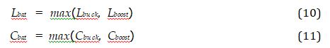
where ∆VDC and Ro are the ripple voltage and output impedance for the boost mode, respectively. However, the bidirectional converter operates in both modes. The values of inductor Lbat and capacitor Cbat are considered as follows:
This section includes all design parameters for GSBD and BSBD converters. The designed parameters are further utilized for PFC control of GSBD and buck control of BSBD converter to charge the EV batteries in G2V mode. Similarly, the designed parameters are utilized for boost control of BSBD and inverter control of GSBD converter to discharge the EV batteries in V2G mode. Control strategies for G2V and V2G modes are discussed in the next section.
You can download the Project files here: Download files now. (You must be logged in).
3. System Control
3.1. Grid-to-Vehicle Control
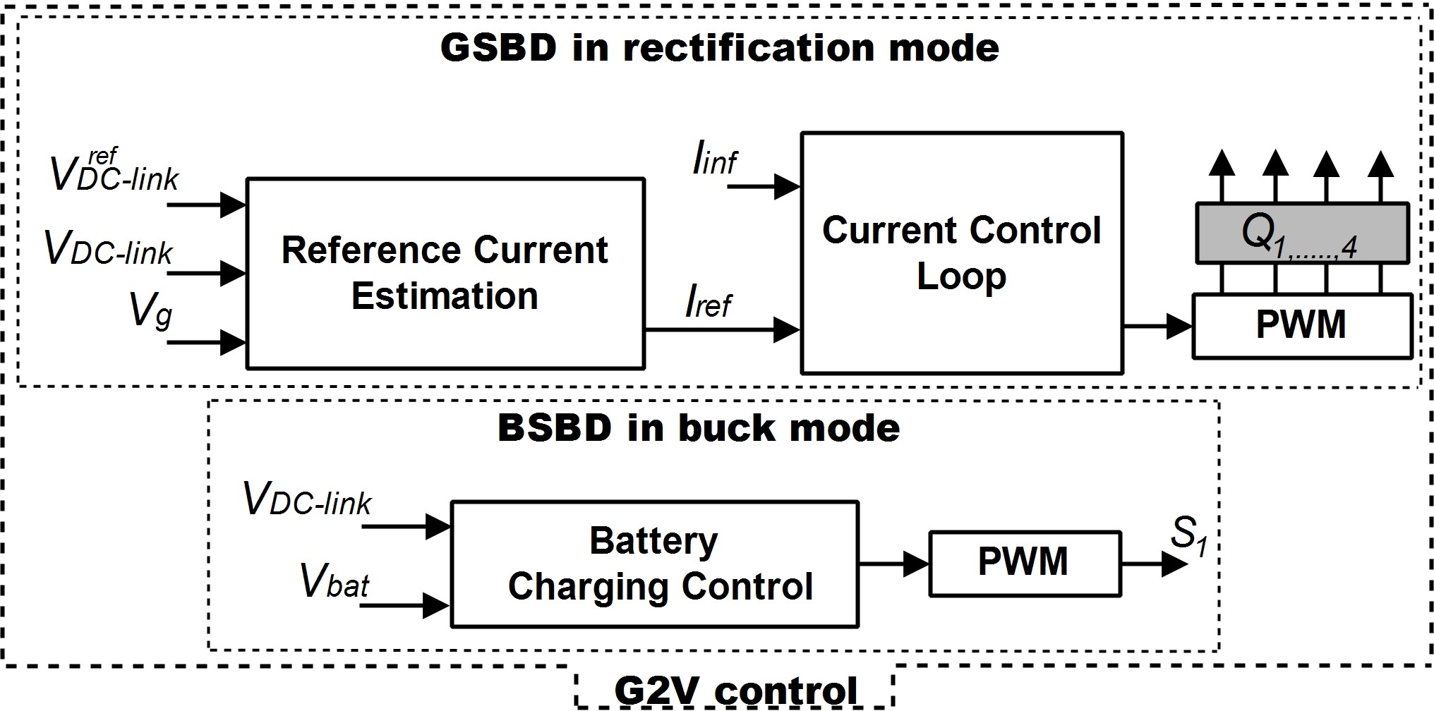
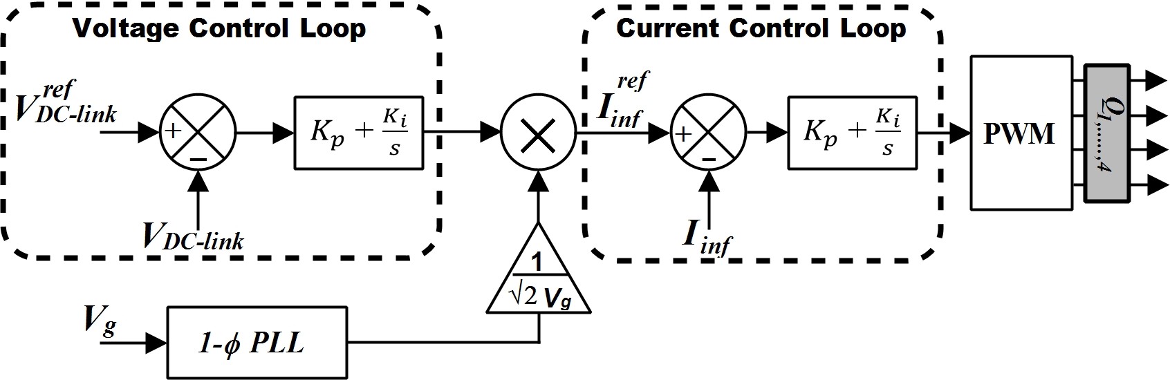
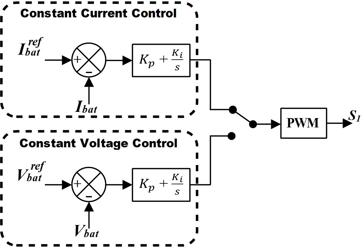
Figure 3 depicts the grid-to-vehicle charging mode control which initiates with the operation of the PFC. In this operation, firstly, the GSBD totem pole PFC works as an active rectifier with sinusoidal current and unity power factor. Secondly, the BSBD converter operates in buck mode to match the voltage level of EV batteries. In rectification mode of totem pole, an interfacing boost inductor is connected in series with the grid to implement the average current control. The average current control using the SiC devices keeps the totem pole PFC operation in CCM mode to avoid the issue of reverse recovery current. In Figure 4, the proposed control includes a voltage control loop. The voltage control loop samples the output, VDC−link, with respect to the predefined reference DC-link voltage, ref DC−link, to produce the reference interfacing inductor current, Ire f . In this process, a single-phase, phase-locked loop (PLL) is also incorporated to keep the input grid current sinusoidal and in phase with the input, Vg, to achieve the unity PF. Furthermore, the obtained Ire f is sampled with the input grid current (Iin f) in current control loop. The obtained voltage reference from the current control loop is provided to a unipolar sinusoidal pulse width modulation (PWM) with the 65 kHz triangular carrier signal to achieve the gate pulses. These gate pulses are provided to the SiC devices used in totem pole PFC for the rectification process. The output of the rectification process is a DC-link voltage which is higher than the EV battery voltage level. Therefore, the buck control on the battery-side bidirectional converter is performed as shown in Figure 5. In buck or charging control, the process occurs in two stages i.e., constant current and constant voltage. Firstly, in the constant current stage, the batteries charge with constant current until the battery voltage level reaches the acclaimed voltage level. Thereupon, the constant voltage is maintained in the second stage until the current flowing into the EV batteries falls below the residual value.
3.2. Vehicle-to-Grid Control
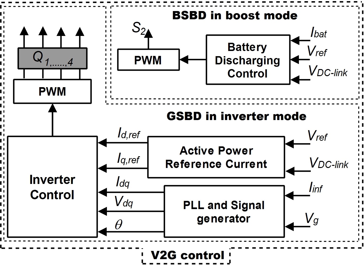
Figure 6 depicts the vehicle-to-grid control in which the BSBD and GSBD converter operates in boost and inverter mode, respectively, to feedback the power into the grid. The V2G mode control starts with discharging of the EV batteries. In this operation, the EV batteries are connected with the BSBD DC-DC converter interfaces the GSBD converter. Firstly, the EV battery voltage level is boosted with the help of battery discharge control to achieve the voltage level at the interfaced DC-link voltage. The DC-link voltage control loop provides the reference current for the active power generation to supply the grid in the battery discharge control.
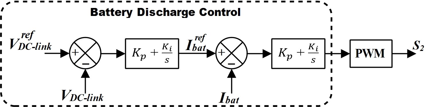
During the discharge process, the EV batteries voltage decreases. Hence, the incre- ment in reference current is necessary to maintain the constant active power generation. Therefore, along with the voltage control loop, a current control loop is also cascaded in battery discharge control, as shown in Figure 7. This discharging operation provides DC-link voltage to operate the grid-side bidirectional converter.
You can download the Project files here: Download files now. (You must be logged in).
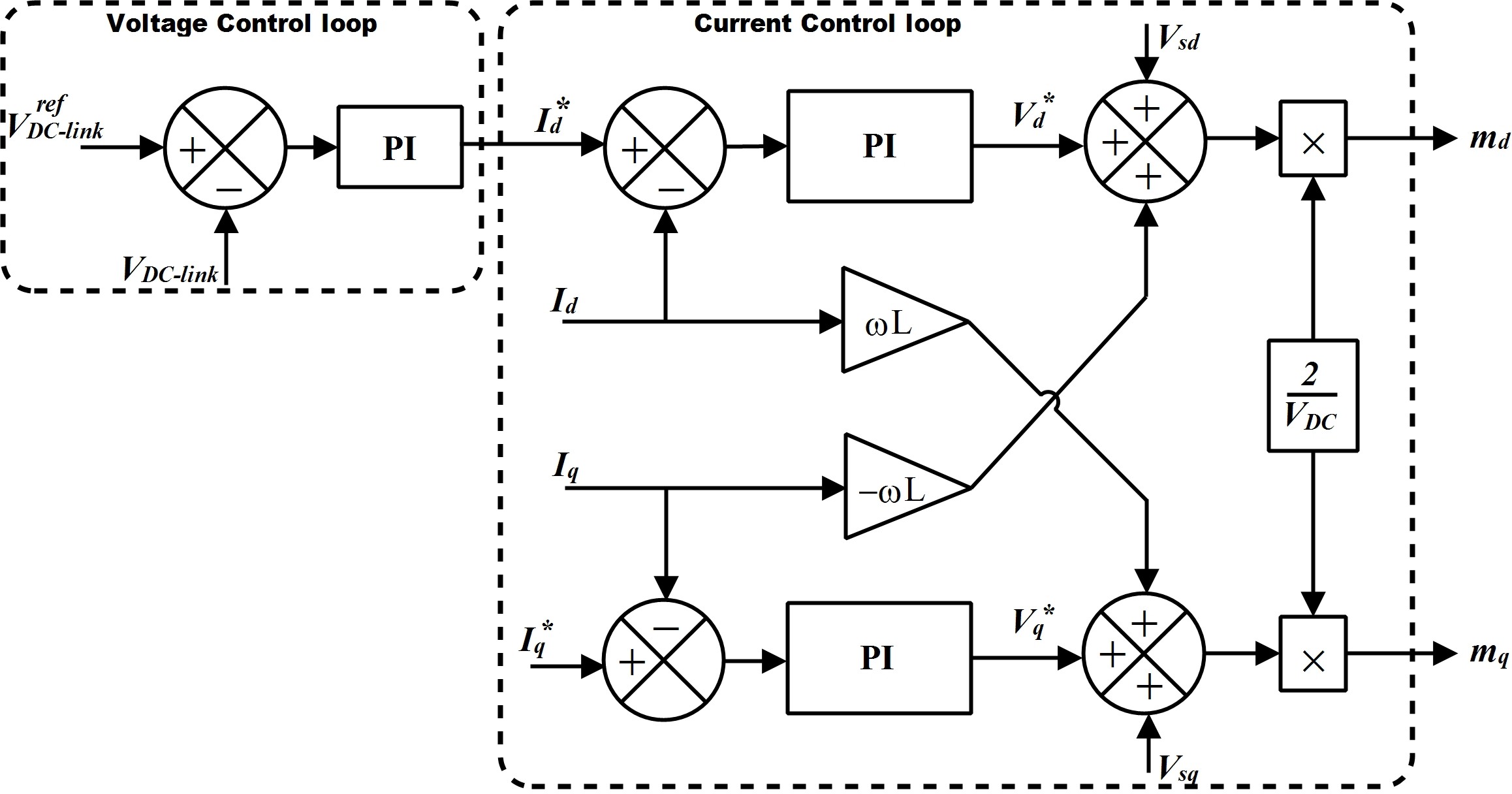
The obtained DC-link voltage acts as an input to the GSBD converter, which works as an inverter in V2G mode. With the help of inverter control, the inverter converts the stored DC power of EV batteries into the AC power to supply back to the grid. The inverter control includes a PLL, voltage control, and current control loop, which obtain in synchronously rotating or dq reference frame. A dq reference frame consists of a direct (d)-axis and quadrature (q)-axis, which deals with active and reactive power control. Furthermore, in inverter control, PLL synchronizes the generated AC current and voltage with the grid current and voltage. Additionally, in voltage control loop, the obtained VDC−link is compared with the predefined Vre f and passed through the proportional–integral (PI) controller. The output of the PI controller provides the active current reference (Ire f ) to generate active power and for unity power factor to keep the reactive current reference (Ire f ), zero. Furthermore, the current control loop generates gate pulses to trigger the inverter to generate the AC power, as shown in Figure 8. The generated AC power is transferred to the grid in V2G mode.
Finally, the designed parameters using system control are utilized to develop a 7.7 kW bidirectional charging and discharging infrastructure. The charging or G2V and discharging or V2G mode performances were verified in MATLAB/Simulink environment which is presented in the next section.
4. Result and Discussion
The study of a 7.7 kW bidirectional charging infrastructure is carried out in MAT- LAB/Simulink environment using the system specifications listed in Table 1, the designed passive components in Table 2, and the control parameters in the Appendix B. Other than this, for charge and discharge purposes, a customized LiFePO4-type lithium-ion battery pack of terminal voltage 72 V and current capacity 106 Ah is considered. Furthermore, the effectiveness of the proposed infrastructure is validated in G2V or charging and V2G or discharging mode to fulfil the targeted specifications such as THD, power factor, and efficiency. In this regard, the BDCI has simulated for t = 4 s, in which the first t = 2 s in G2V mode and V2G mode in another t = 2 s. Furthermore, the detailed performances of both modes have been discussed in the following subsections.
Table 2. Designed passive components for BDCI.
Passive Components Value
Lin f 5 mH
CDC 8200 µF
Lbat 5 mH
Cbat 20,000 µF
4.1. Performance in G2V Mode
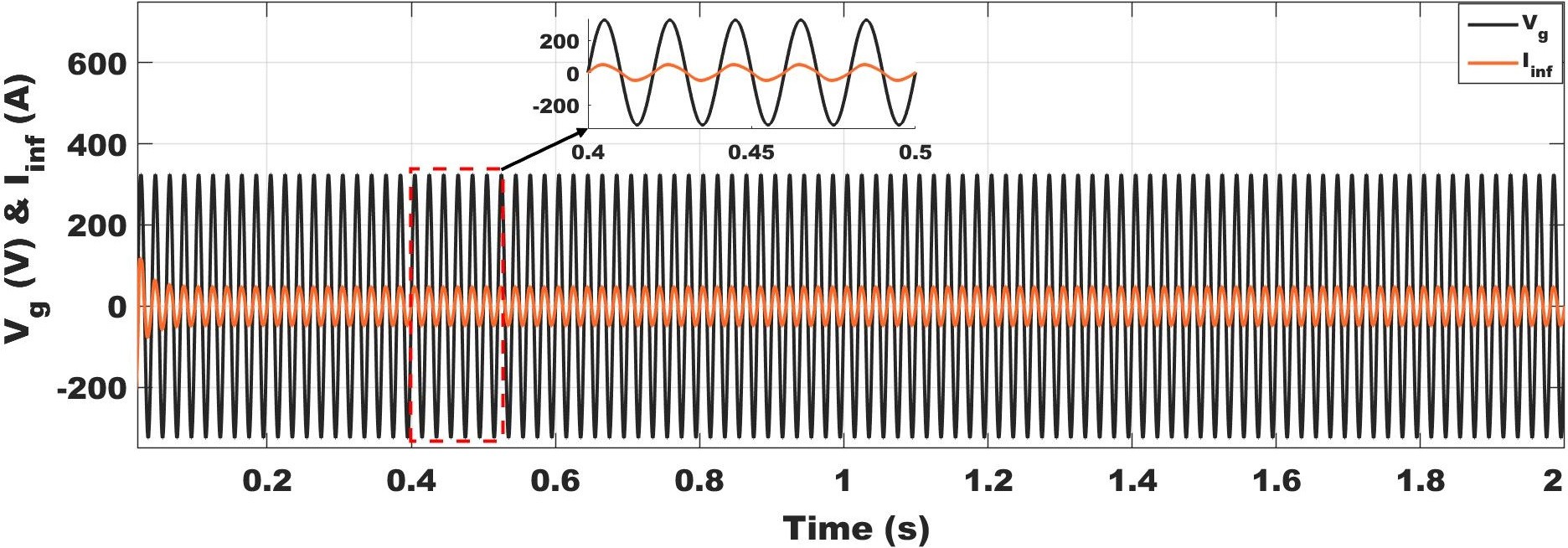
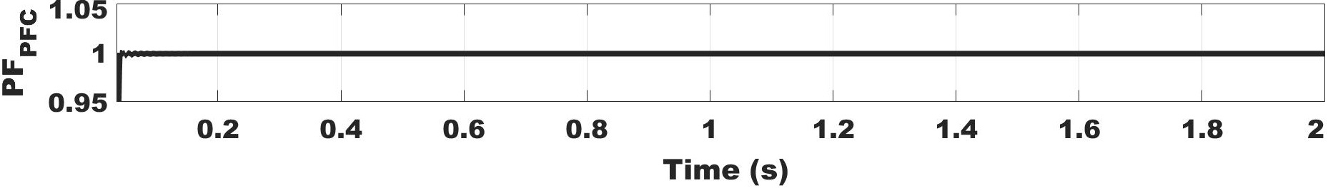
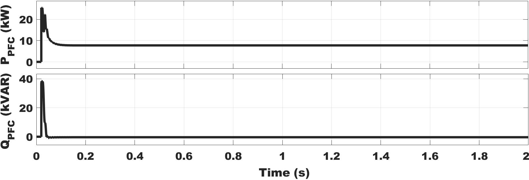
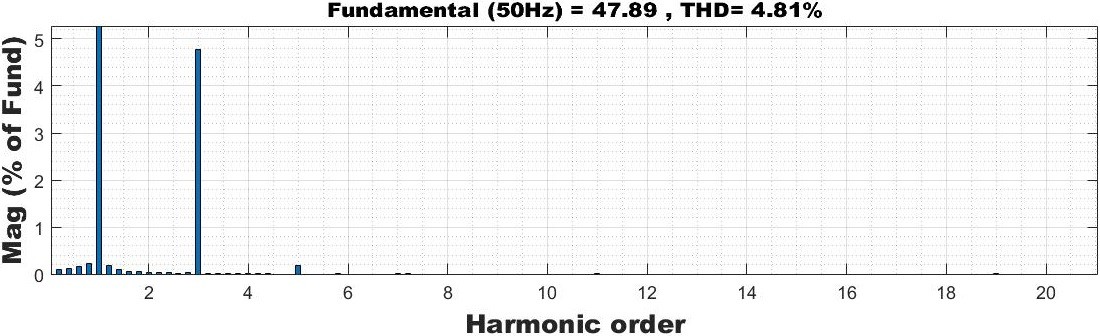
In G2V mode, the charging process takes place from the grid to the EV batteries using grid- and battery-side bidirectional converters. In this mode, it is expected that the grid current and voltage should be sinusoidal and should achieve a unity power factor. Additionally, the battery-side voltage or current should be constant. Figure 9 shows that the input grid current, Iin f , is in phase with the input grid voltage, Vg. Simultaneously, Figures 10 and 11 show that the power factor is near to unity, or in other terms, the obtained active and reactive powers are approximately rated and zero, respectively, whereas, in Figure 12, the THD present in Iin f is within the IEEE standard 519, which shows the effectiveness of the PFC control and utilization of high switching frequency with the SiC devices in the totem pole converter for rectification process.
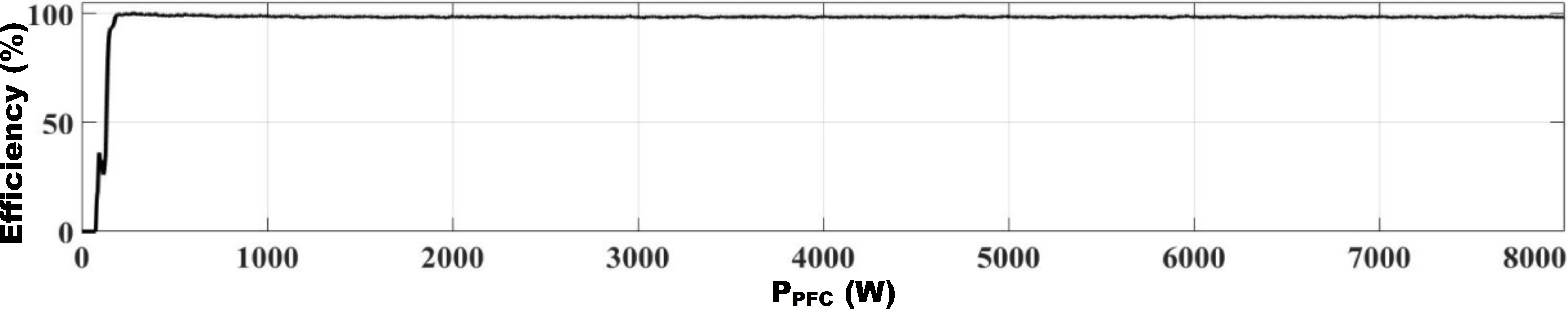
Here, the power loss for the totem pole PFC is estimated using (12) and there compo- nents are discussed in Appendix A [48].
![]()
where PL,PFC, PL,ind, and PL,co are the power loss in PFC, interfacing inductor, and DC-link capacitor, respectively, whereas PL,sw and PL,cond are the switching and conduction loss in the SiC switch, respectively . Since the interfacing inductor loss is low, it will be neglected for all current level. The power loss of the switching device for the totem pole PFC is calculated using an online tool, i.e., UnitedSiC FET-Jet Calculator [49], as mentioned in [50]. Additionally, the DC-link capacitor loss is calculated using (A2) and, altogether, other losses are presented in Table 3. In Figure 13, the simulation-based efficiency is presented on the basis of the input and output power of the totem pole PFC rectifier, which matches with the online calculated measure. Furthermore, as an output of the rectification process, a DC-link voltage is obtained for the battery-side bidirectional DC-DC converter, where ∆VDC−link is also achieved within the expected limit, as shown in Figure 14.
Table 3. Power loss calculation using UnitedSiC FET-Jet Calculator.
| Loss Components | Value |
| Interfacing inductor loss | – |
| DC-link capacitor loss | 5.26 W |
| Switching loss | 52.4 W |
| Conduction loss | 70.8 W |
| Total power loss | 128.46 W |
| Output-rated power | 7700 W |
| Efficiency | 98.38% |
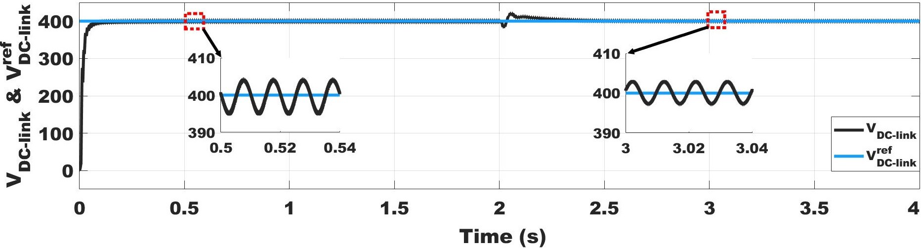
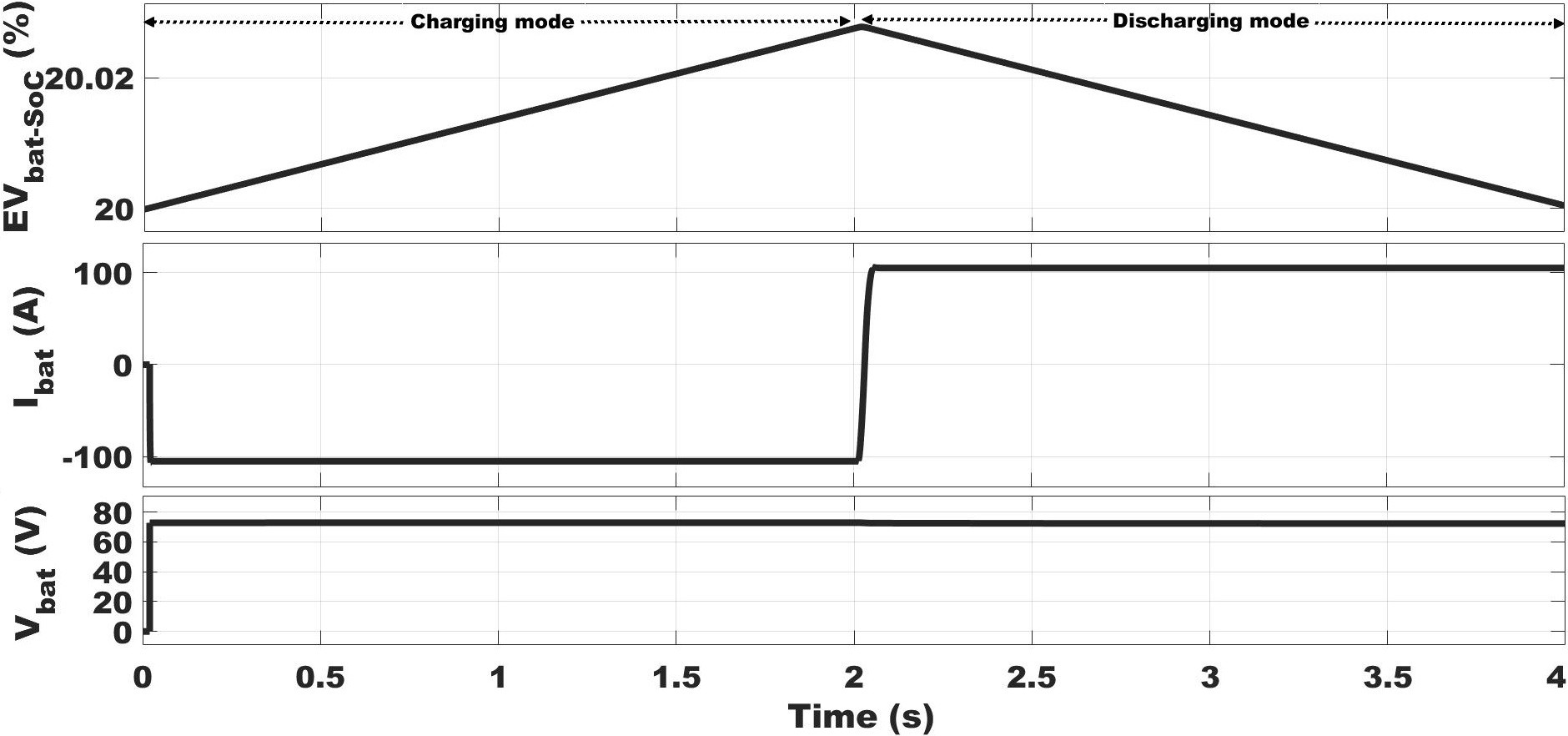
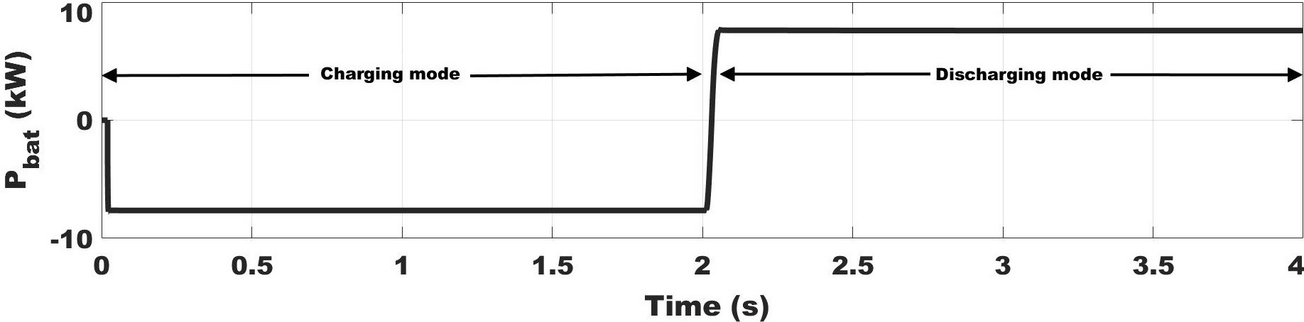
In Figure 14, the performance of VDC−link in rectification mode is presented from t = 0 s to t = 2 s. Furthermore, the obtained VDC−link is provided to the BSBD converter to charge the EV batteries using buck mode control. The charging performances of the EV batteries are obtained for t = 2 s. In this duration, the performance of the EV batteries is presented in terms of the state of charge (SoC) of the battery, the charging current, and the terminal voltage, as shown in Figure 15. In the charging mode section of Figure 15, the increment in SoC and the negative value of current shows the charging of the EV batteries. Similarly, the instantaneous energy or power stored in the EV batteries are illustrated in Figure 16, where the negative power shows the charging of the EV batteries.
You can download the Project files here: Download files now. (You must be logged in).
4.2. Performance in V2G Mode
In V2G or discharging mode operation, the flow of power is from EV batteries to the grid. This process takes place in two stages. In the first stage, the EV batteries participate in achieving the VDC−link from the Vbat using BSBD converter. Due to the higher voltage level of the VDC−link then Vbat, BSBD converter operates using boost mode control. As a result of the boost mode control, the performance of VDC−link is shown in Figure 14 from t = 2 s to t = 4 s. Simultaneously, the performances of EV batteries in the boost mode are presented in the discharging section of Figure 15.
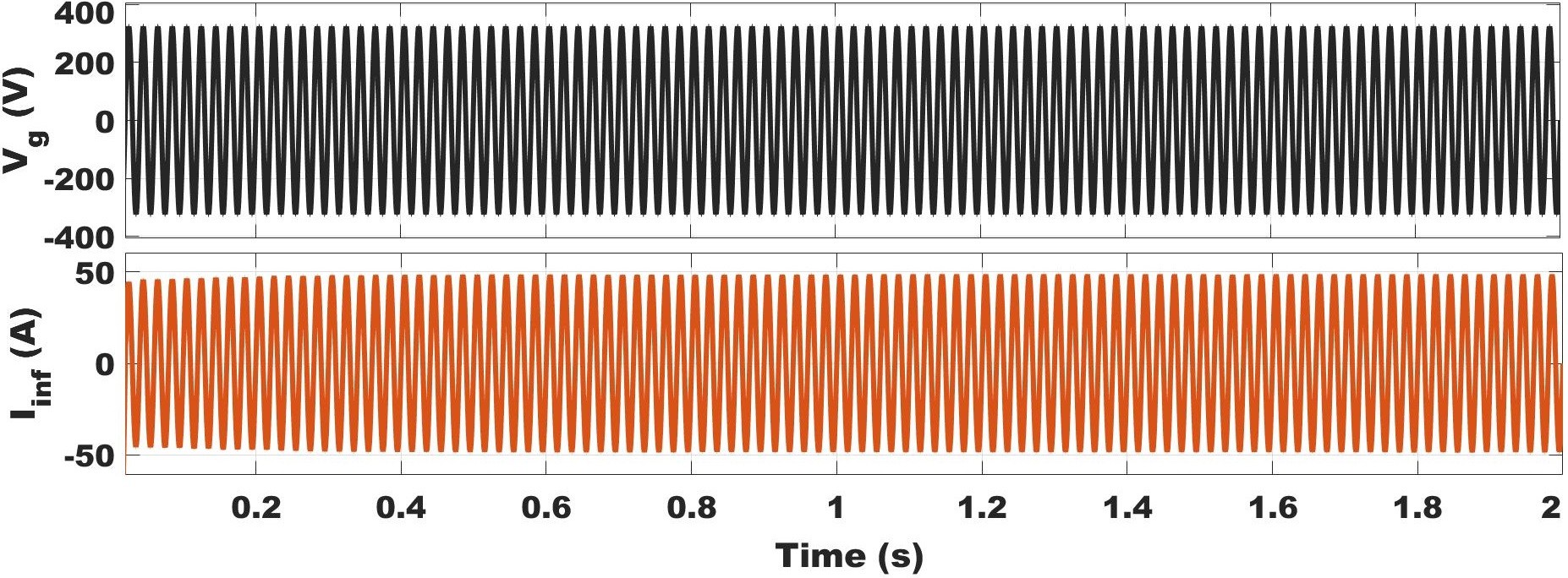
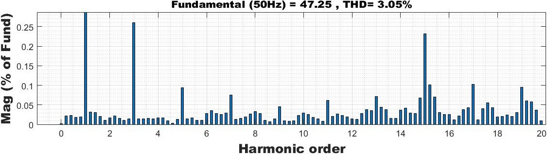
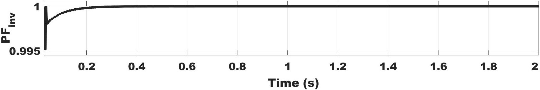
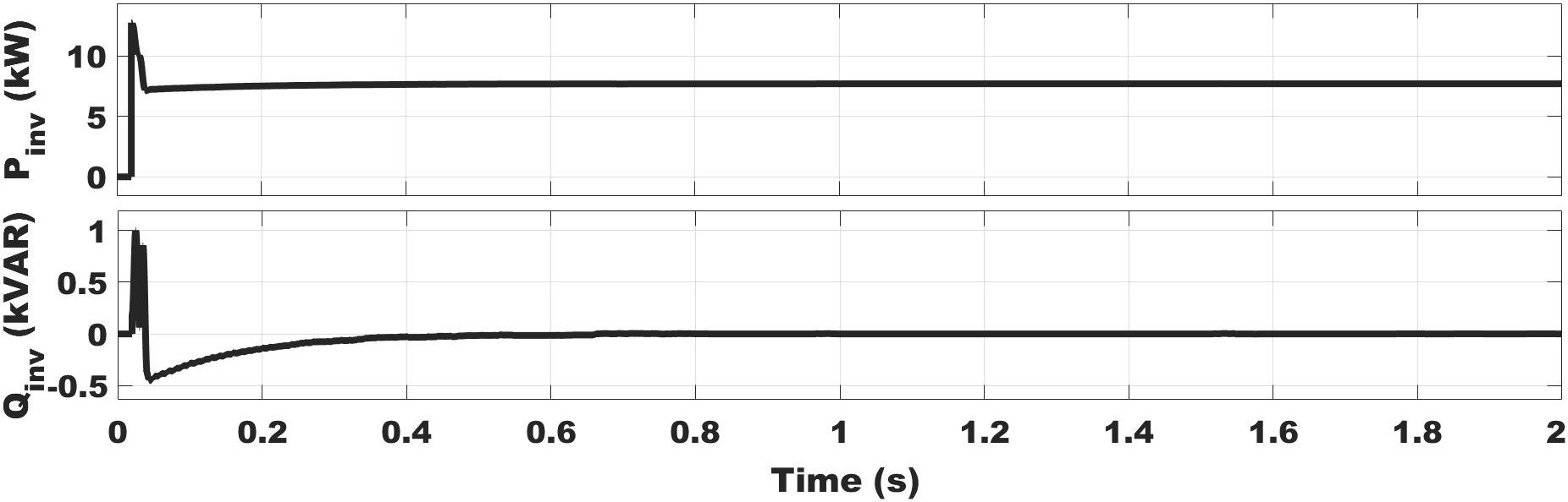
In Figure 15, the performance of EV batteries in discharging section is presented in terms of SoC, discharging current, and terminal voltage, where positive current and negative slope of SoC indicates the discharging process. Similarly, the discharging mode section in Figure 16 have positive instantaneous battery power, Pbat, from t = 2 s to t = 4 s, which shows the power discharge from the EV battery towards the grid in V2G mode. At the end of the first stage of V2G mode, the DC power is transferred to the grid using GSBD converter in inverter mode. In the inverter mode of operation, the obtained VDC−link acts as a DC input (voltage and current) and provides AC output (voltage and current) for the grid using inverter control. Figure 17 illustrates the feed in voltage and current for the grid. As expected, the targeted THD according to IEEE standard 519 and unity PF are achieved using inverter control strategy, as shown in Figures 18 and 19. Similarly, Figure 20 illustrates that the targeted transferred active and reactive powers that are Prat and zero, respectively, have been achieved from the developed bidirectional totem pole charging infrastructure.
You can download the Project files here: Download files now. (You must be logged in).
5. Conclusions
Charging infrastructure is being developed to compensate for the fuel crisis through EV transportation support. Additionally, the charging infrastructure is utilized to support the grid during peak power demand to minimize the overall installation cost and owner’s benefit. Therefore, in charging or G2V mode, a GSBD totem pole and BSBD DC-DC con- verter are included to operate in rectifier and buck mode, respectively. On the other hand, in discharging or V2G mode, GSBD and BSBD converters are employed in inverter and boost mode, respectively. In this G2V and V2G mode, the grid-side converter includes SiC (WBG device) as a switch capable of utilizing the higher switching frequency during PFC opera- tion. The use of SiC devices keeps the PFC operation in CCM mode and avoids the issue of reverse recovery current. Additionally, the use of a higher switching frequency lowers the size of the interfacing boost inductor as well as lesser space and thermal management. The analysis on the switching frequency design also helps to choose its optimum value to operate the PFC for EV charging with higher efficiency and lower THD. Furthermore, A 7.7 kW BDCI is implemented in the LTSpice and MATLAB/Simulink environment. The dynamic performances of the system strengthen the effectiveness of the control strategies used in G2V and V2G mode at the designed parameters and selected system specifications in BDCI. Additionally, the system performance also shows that the targeted power factor and THD are achieved and within the IEEE standards.
Author Contributions: Conceptualization, V.K. and K.Y.; methodology, V.K. and K.Y.; software, V.K. and K.Y.; validation, V.K. and K.Y.; formal analysis, V.K.; investigation, V.K.; resources, V.K. and K.Y.; writing—original draft preparation, V.K.; writing—review and editing, V.K. and K.Y.; visualization,
V.K. and K.Y.; supervision, V.K. and K.Y. All authors have read and agreed to the published version of the manuscript.
Funding: This research was supported by National Research Foundation of Korea (NRF) funded by the Ministry of Science, ICT & Future Planning.
Institutional Review Board Statement: Not applicable.
Informed Consent Statement: Not applicable.
Data Availability Statement: Not applicable.
Acknowledgments: The author would like to thank the Ministry of Science, ICT & Future Planning under grant number NRF-2020R1F1A1048246.
Conflicts of Interest: The authors declare no conflict of interest.
Appendix A. Power Loss Calculation
Power Loss Calculation for PFC is calculated using the following—Equation [48]:
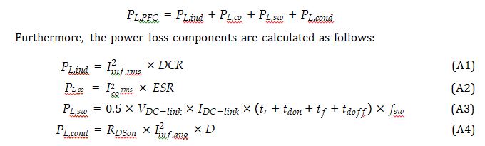
where Iin f ,rms, Iin f ,avg, Ico,rms, IDC−link, and D are the rms interfacing inductor current, av- erage interfacing inductor current, rms DC-link capacitor current, PFC output current, and duty ratio, respectively. Parameters DCR (DC resistance) and ESR (equivalent series resistance) have been selected from the data sheet of the selected interfacing inductor and DC-link capacitor, respectively. Additionally, tr (rise time), tdon (turn-on delay time), tdo f f (turn-off delay time), and t f (fall time) are the data sheet parameters of the SiC devices chosen for power loss calculation using an online tool, i.e., UnitedSiC FET-Jet Calculator.
Appendix B. Control Parameters In G2V mode
For PFC control: voltage control loop kp = 0.8 and ki = 5.4; current control loop kp = 0.1
and ki = 3.2; PLL parameters: kp = 4 and ki = 1040. For battery charging: constant current control kp = 7 and ki = 510; constant voltage control kp = 0.05 and ki = 10; sampling time: 1/ fSW/200.
In V2G mode
For battery discharging: voltage control loop kp = 0.02 and ki = 3; current control loop
kp = 0.05 and ki = 10. For inverter control: voltage control loop kp = 15 and ki = 265; current control loop kp = 1.5 and ki = 10. PLL parameters: kp = 180 and ki = 3200; sampling time: 1/ fSW/200.
References
- Bohn, T. Plug-in Electric (PEV) Standards, Upcoming PEVs/Features, Charging System Overview. Technical Report. 2012. Available online: https://www.yumpu.com/en/document/view/6096860/plug-in-electric-vehicle-pev-standards-upcoming- pevs-eere (accessed on 29 December 2021).
- Yuan, J.; Dorn-Gomba, L.; Callegaro, A.D.; Reimers, J.; Emadi, A. A Review of Bidirectional On-Board Chargers for Electric IEEE Access 2021, 9, 51501–51518. [CrossRef]
- Yilmaz, M.; Krein, P.T. Review of Battery Charger Topologies, Charging Power Levels, and Infrastructure for Plug-In Electric and Hybrid Vehicles. IEEE Trans. Power Electron. 2013, 28, 2151–2169. [CrossRef]
- Lacroix, S.; Laboure, E.; Hilairet, M. An integrated fast battery charger for Electric Vehicle. In Proceedings of the 2010 IEEE Vehicle Power and Propulsion Conference, Lille, France, 1–3 September 2010; 1–6. [CrossRef]
- Grenier, ; Hosseini Aghdam, M.G.; Thiringer, T. Design of on-board charger for plug-in hybrid electric vehicle. In Proceedings of the 5th IET International Conference on Power Electronics, Machines and Drives (PEMD 2010), Brighton, UK, 19–21 April 2010; 1–6. [CrossRef]
- Navinchandran, S.; Sujith, M. Bidirectional On-Board Single Phase Electric Vehicle Charger with High Gain Boost Converter for V2G Application. In Proceedings of the 2020 Fourth International Conference on Inventive Systems and Control (ICISC), Coimbatore, India, 8–10 January 2020; 363–368. [CrossRef]
- Yong, J.Y.; Ramachandaramurthy, V.K.; Tan, K.M.; Mithulananthan, N. Bidirectional electric vehicle fast charging station with novel reactive power compensation for voltage Int. J. Electr. Power Energy Syst. 2015, 64, 300–310. [CrossRef]
- Skouras, T.A.; Gkonis, P.K.; Ilias, C.N.; Trakadas, P.T.; Tsampasis, E.G.; Zahariadis, T.V. Electrical Vehicles: Current State of the Art, Future Challenges, and Perspectives. Clean 2020, 2, 1–16. [CrossRef]
- Youn, H.S.; Park, J.S.; Park, K.B.; Baek, J.I.; Moon, G.W. A Digital Predictive Peak Current Control for Power Factor Correction With Low-Input Current IEEE Trans. Power Electron. 2016, 31, 900–912. [CrossRef]
- Martinez, ; Enjeti, P. A high-performance single-phase rectifier with input power factor correction. IEEE Trans. Power Electron. 1996, 11, 311–317. [CrossRef]
- Ferrari de Souza, ; Barbi, I. A new ZVS semiresonant high power factor rectifier with reduced conduction losses. IEEE Trans. Ind. Electron. 1999, 46, 82–90. [CrossRef]
- Wang, C.M. A novel zero-Voltage-switching PWM boost rectifier with high power factor and low conduction losses. IEEE Trans. Electron. 2005, 52, 427–435. [CrossRef]
- Liu, ; Davari, P.; Blaabjerg, F. An Optimized Hybrid Modulation Scheme for Reducing Conduction Losses in Dual Active Bridge Converters. IEEE J. Emerg. Sel. Top. Power Electron. 2021, 9, 921–936. [CrossRef]
- Huiping, Y.; Lei, X.; Shiben, M.; Zhifu, W. The study of the on-board charger with the bridgeless PFC. In Proceedings of the 2011 4th International Conference on Power Electronics Systems and Applications, Hong Kong, China, 8–10 June 2011; 1–3. [CrossRef]
- Kushwaha, R.; Singh, B. Power Factor Improvement in Modified Bridgeless Landsman Converter Fed EV Battery Charger. IEEE Trans. Veh. Technol. 2019, 68, 3325–3336. [CrossRef]
- Dixit, A.; Pande, K.; Gangavarapu, S.; Rathore, A.K. DCM-Based Bridgeless PFC Converter for EV Charging Application. IEEE Emerg. Sel. Top. Ind. Electron. 2020, 1, 57–66. [CrossRef]
- Li, S.; Deng, J.; Mi, C.C. Single-Stage Resonant Battery Charger With Inherent Power Factor Correction for Electric Vehicles. IEEE Veh. Technol. 2013, 62, 4336–4344. [CrossRef]
- Singh, ; Kushwaha, R. An EV battery charger with power factor corrected bridgeless zeta converter topology. In Proceedings of the 2016 7th India International Conference on Power Electronics (IICPE), Patiala, India, 17–19 November 2016; pp. 1–6. [CrossRef]
- Pinto, G.; Monteiro, V.; Gonçalves, H.; Exposto, B.; Pedrosa, D.; Couto, C.; Afonso, J.L. Bidirectional battery charger with Grid-to-Vehicle, Vehicle-to-Grid and Vehicle-to-Home technologies. In Proceedings of the IECON 2013—39th Annual Conference of the IEEE Industrial Electronics Society, Vienna, Austria, 10–13 November 2013; pp. 5934–5939. [CrossRef]
- Kisacikoglu, C.; Kesler, M.; Tolbert, L.M. Single-Phase On-Board Bidirectional PEV Charger for V2G Reactive Power Operation. IEEE Trans. Smart Grid 2015, 6, 767–775. [CrossRef]
- Fahem, K.; Chariag, D.E.; Sbita, L. On-board bidirectional battery chargers topologies for plug-in hybrid electric vehicles. In Proceedings of the 2017 International Conference on Green Energy Conversion Systems (GECS), Hammamet, Tunisia, 23–25 March 2017; pp. 1–6. [CrossRef]
- Bolte, S.; Schafmeister, F.; Böcker, J. Bidirectional Resonant Converter with Integrated Magnetics for On-Board Chargers. In Proceedings of the 2019 IEEE 28th International Symposium on Industrial Electronics (ISIE), Vancouver, BC, Canada, 12–14 June 2019; pp. 770–774. [CrossRef]
- Nassary, M.; Orabi, M.; Ghoneima, M.; El-Nemr, M.K. Single-Phase Isolated Bidirectional AC-DC Battery Charger for Electric Vehicle—Review. In Proceedings of the 2019 International Conference on Innovative Trends in Computer Engineering (ITCE), Aswan, Egypt, 2–4 February 2019; pp. 581–586. [CrossRef]
- Sharma, ; Sharma, S. Review of power electronics in vehicle-to-grid systems. J. Energy Storage 2019, 21, 337–361. [CrossRef]
- Blaabjerg, ; Wang, H.; Vernica, I.; Liu, B.; Davari, P. Reliability of Power Electronic Systems for EV/HEV Applications. Proc. IEEE 2021, 109, 1060–1076. [CrossRef]
- Choi, ; Han, D.; Morris, C.T.; Sarlioglu, B. Achieving high efficiency using SiC MOSFETs and reduced output filter for grid-connected V2G inverter. In Proceedings of the IECON 2015—41st Annual Conference of the IEEE Industrial Electronics Society, Yokohama, Japan, 9–12 November 2015; pp. 003052–003057. [CrossRef]
- Xue, L.; Shen, Z.; Boroyevich, D.; Mattavelli, P.; Diaz, D. Dual Active Bridge-Based Battery Charger for Plug-in Hybrid Electric Vehicle With Charging Current Containing Low Frequency Ripple. IEEE Power Electron. 2015, 30, 7299–7307. [CrossRef]
- Zhang, Z.; Yao, K.; Ke, G.; Zhang, K.; Gao, Z.; Wang, Y.; Ren, X.; Chen, Q. SiC MOSFETs Gate Driver With Minimum Propagation Delay Time and Auxiliary Power Supply With Wide Input Voltage Range for High-Temperature IEEE J. Emerg. Sel. Top. Power Electron. 2020, 8, 417–428. [CrossRef]
- Huang, Q.; Huang, A.Q. Review of GaN totem pole bridgeless PFC. Cpss Power Electron. Appl. 2017, 2, 187–196. [CrossRef]
- Liu, ; Lee, F.C.; Li, Q.; Yang, Y. Design of GaN-based MHz totem pole PFC rectifier. IEEE J. Emerg. Sel. Top. Power Electron. 2016, 4, 799–807. [CrossRef]
- Li, B.; Li, Q.; Lee, F.C.; Liu, Z.; Yang, Y. A High-Efficiency High-Density Wide-Bandgap Device-Based Bidirectional On-Board IEEE J. Emerg. Sel. Top. Power Electron. 2018, 6, 1627–1636. [CrossRef]
- Wang, ; Jiang, C.; Lei, B.; Teng, H.; Bai, H.K.; Kirtley, J.L. Power-Loss Analysis and Efficiency Maximization of a Silicon-Carbide MOSFET-Based Three-Phase 10-kW Bidirectional EV Charger Using Variable-DC-Bus Control. IEEE J. Emerg. Sel. Top. Power Electron. 2016, 4, 880–892. [CrossRef]
- Tang, ; Lu, J.; Wu, B.; Zou, S.; Ding, W.; Khaligh, A. An Integrated Dual-Output Isolated Converter for Plug-in Electric Vehicles. IEEE Trans. Veh. Technol. 2018, 67, 966–976. [CrossRef]
- Wei, ; Zhu, D.; Xie, H.; Shao, J. A 6.6kW high power density Bidirectional EV on-board charger based on SiC MOSFETs. In Proceedings of the PCIM Europe 2019, International Exhibition and Conference for Power Electronics, Intelligent Motion, Renewable Energy and Energy Management, Nuremberg, Germany, 7–9 May 2019; pp. 246–252.
- Jia, ; Wu, H.; Yang, L.; Xu, X.; Liu, Y.; Yang, F.; Xing, Y. Characterization and Optimal Control of totem pole PFC Converter With High Frequency GaN HEMTs and Low Frequency Si Diodes. IEEE Trans. Ind. Electron. 2021, 68, 10740–10749. [CrossRef]
- Su, B.; Lu, Z. An Interleaved totem pole Boost Bridgeless Rectifier With Reduced Reverse-Recovery Problems For Power Factor IEEE Trans. Power Electron. 2010, 25, 1406–1415. [CrossRef]
- Zhou, L.; Wu, Y.; Honea, J.; Wang, Z. High-efficiency True Bridgeless Totem Pole PFC based on GaN HEMT: Design Challenges and Cost-effective Solution. In Proceedings of the PCIM Europe 2015, International Exhibition and Conference for Power Electronics, Intelligent Motion, Renewable Energy and Energy Management, Nuremberg, Germany, 19–20 May 2015; 1–8.
- Liu, Z.; Li, B.; Lee, F.C.; Li, Q. High-Efficiency High-Density Critical Mode Rectifier/Inverter for WBG-Device-Based On-Board Charger. IEEE Ind. Electron. 2017, 64, 9114–9123. [CrossRef]
- Huang, Q.; Ma, Q.; Liu, P.; Huang, A.Q.; de Rooij, M.A. 99% Efficient 2.5-kW Four-Level Flying Capacitor Multilevel GaN totem pole IEEE J. Emerg. Sel. Top. Power Electron. 2021, 9, 5795–5806. [CrossRef]
- Yu, Z.; Xia, ; Ayyanar, R. A Simple ZVT Auxiliary Circuit for totem pole Bridgeless PFC Rectifier. IEEE Trans. Ind. Appl. 2019, 55, 2868–2878. [CrossRef]
- Huang, ; Yu, R.; Ma, Q.; Huang, A.Q. Predictive ZVS Control with Improved ZVS Time Margin and Limited Variable Frequency Range for a 99% Efficient, 130-W/in3 MHz GaN totem pole PFC Rectifier. IEEE Trans. Power Electron. 2019, 34, 7079–7091. [CrossRef]
- Liu, ; Wiener, P. Optimal Design for High Frequency GaN-Based Totem Pole PFC; GaN Systems Inc.: Kanata, ON, Canada, 2019.
- Yu, Y.; Gong, X.; Wang, G.; Bhardwaj, M. Designing a High-Power Bidirectional AC/DC Power Supply Using SiC FET. 2020;
- 1–25. Available online: www.ti.com/psds (accessed on 1 February 2022).
- Li, ; Zhang, Z.; Wang, S.; Tang, J.; Ren, X.; Chen, Q. A 300-kHz 6.6-kW SiC Bidirectional LLC Onboard Charger. IEEE Trans. Ind. Electron. 2020, 67, 1435–1445. [CrossRef]
- Power Factor Correction (PFC) Handbook; SCILLC: Steel City, PA, USA,
- Xu, D.; Zhang, J.; Chen, W.; Lin, J.; Lee, F. Evaluation of output filter capacitor current ripples in single phase PFC converters. In Proceedings of the Power Conversion Conference-Osaka 2002 (Cat. No.02TH8579), Osaka, Japan, 2–5 April 2002; Volume 3,
- 1226–1231. [CrossRef]
- Yao, K.; Wang, ; Guo, J.; Chen, K. Critical Conduction Mode Boost PFC Converter with Fixed Switching Frequency Control. IEEE Trans. Power Electron. 2018, 33, 6845–6857. [CrossRef]
- Abdel-Rahman, ; Stückler, F.; Siu, K. PFC Boost Converter Design Guide; Infineon Application Note; 2016; Volume 2. Available online: http://www.personal.psu.edu/ahy5028/coiling/InfineonPFCCCMBoostConverterDesignGuide.pdf (accessed on 1 February 2022).
- Performance Calculator of Single-Phase SiC Based PFC in CCM. Available online: https://unitedsic.com/ fet-jet/ (accessed on 1 February 2022).
- Zhu, M. Enabling 99.3% Efficiency in 3.6 kW Totem Pole PFC Using New 750 V Gen 4 SiC FETs. 2021. Available online: https:// com/appnotes/Enabling-efficiency-in-Totem-pole-PFC-using-750V-Gen-4-SiC-FETs.pdf (accessed on 1 February 2022).
You can download the Project files here: Download files now. (You must be logged in).


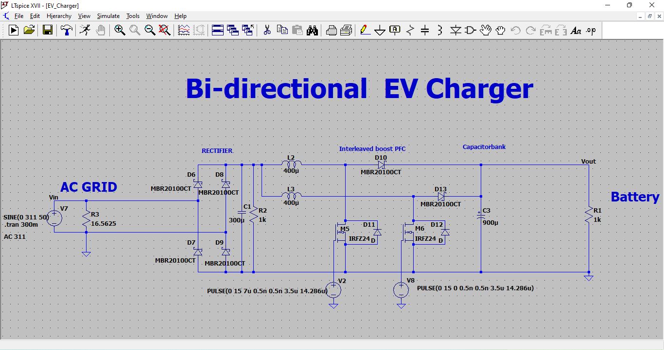
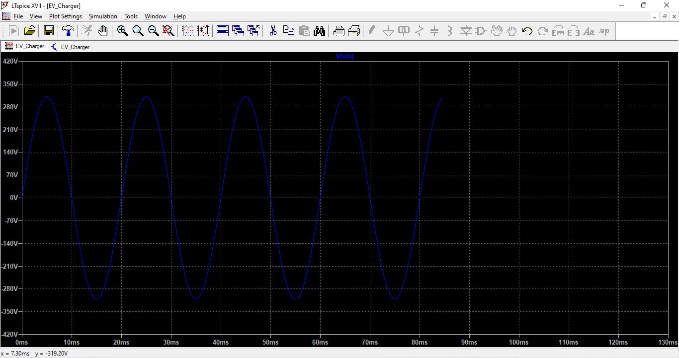
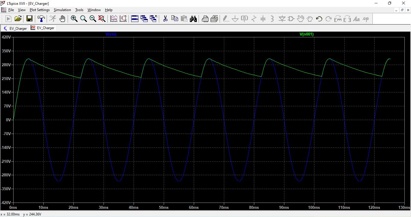
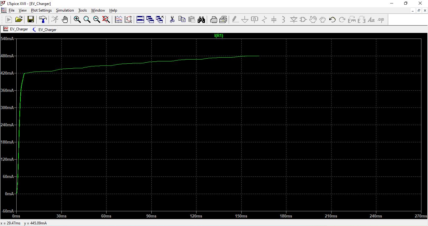
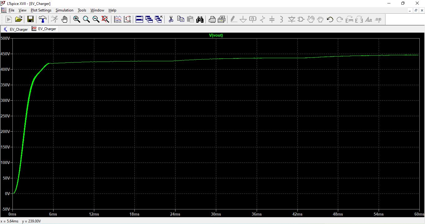
Hello, why the design in ltspice gives out only 470V and 2.7kW though?
The reason my LTspice design is showing about 470 V and only ~2.7 kW is most likely because the converter is not drawing the rated input current required for 7.7 kW operation.
Even though the DC-link voltage can rise above the 400 V reference, the transferred power is mainly controlled by the current control loop. Based on a 230 V input, the charger should draw roughly 34 A RMS to achieve 7.7 kW, but the simulation indicates a much lower current (around 11–12 A), which limits the power to ~2.7 kW.
So I am still improving this research to get the required output current.
This was my research project for the Electric Vehicles and its outputs are achieve able upto 80% and I am still working on this project in the next phase to improve its accuracy. Also, I am waiting for the budget which need to approve from my supervisor/professor for the further improvements in this project.
The reason your LTspice design is showing about 470 V and only ~2.7 kW is most likely because the converter is not drawing the rated input current required for 7.7 kW operation.
Even though the DC-link voltage can rise above the 400 V reference, the transferred power is mainly controlled by the current control loop. Based on a 230 V input, the charger should draw roughly 34 A RMS to achieve 7.7 kW, but the simulation indicates a much lower current (around 11–12 A), which limits the power to ~2.7 kW.
So I am still improving this research to get the required output current.