

Assessing the Feasibility of Small-Scale Wind Turbines in Uzbekistan
Author: Waqas Javaid
Abstract—Global energy demand and climate urgency lead to the transition to renewables. Uzbekistan relies on dwindling natural gas and has consumption and pollution challenges. This paper investigates the use of small wind turbines (SWTs) to provide sustainable energy to rural, off-grid regions of Uzbekistan. The system has a DC generator and an ANFIS-controlled buck converter to enhance efficiency and reliability. The performance is simulated through theoretical analysis, simulation, and experiments under various wind speeds. Uzbekistan’s Bukhara region has an average capability to generate 6.3 kW using wind. ANFIS-controlled buck converters ensure maximum power conversion efficiency making SWT ideal for rural electrification. SWT can lower the cost of electricity through an economic analysis that indicates SWT can be used as an efficient substitute to the conventional sources. Combination of SWT along with wind and sunlight improves off-grid feasibility. The research indicates SWT has the capability to lower the consumption of fossil fuel and carbon emissions to ensure energy security in Uzbekistan.
Keywords—Wind turbine, ANFIS, Buck converter
I. Introduction (Heading 1)
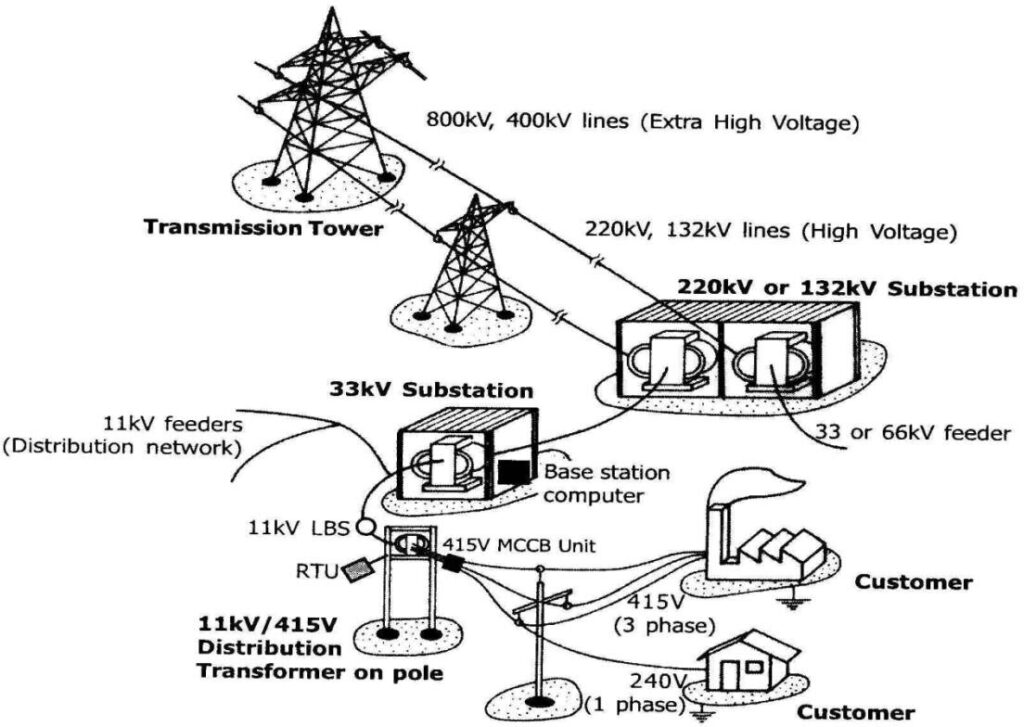
The shift to renewables is a global need to address the emissions of the greenhouse gases, ensure energy security, and ensure sustainable economic growth [1]. Wind energy is the best option based on availability, scalability, and affordability. Uzbekistan has a highly gas-dependent economy and an unprecedented transition to depleting reserves accompanied by increasing energy demand. Population projections is said to double by 2100 [2], creating the need to establish an integrated sustainable energy solution, in rural areas where the grid does not penetrate.
Uzbekistan’s historical use of the fossil fuel has contributed to the deterioration of the environment through carbon emissions and air pollution. Natural gas has dominated the sector within the country to the tune of about 85% contribution to the sector [3]. As the demand for the energy has increased and gas reserve dwindled, the government has begun exploiting other types of the sector to diversify. Wind has risen to be part of Uzbekistan’s sustainable sector, an emissions-free source.
In response to the challenges outlined above, Uzbekistan has made some initiatives and policies to encourage the use of the use of renewables. The vision of the government to create a “Green Uzbekistan” has the objective to increase the percentage of renewables used to produce electricity to 25% by 2030 [4]. Wind power has an important role to play under the vision, particularly in rural remote areas where the grid system is underdevelopment. Decentralized options such as SWTs can encourage the reliability and security of the electricity as well as the minimization of natural losses that are common to large centralized power stations.
Large-scale wind farms like the Zarafshan 500 MW Wind Power Plant reflect Uzbekistan’s intention to look to wind power [5]. The logistics and expense of large wind farms, however, reflect the necessity to look to decentralized solutions like SWTs. With the average wind speed range being 6.5 to 7.5 m/s in highly prospective areas [6], SWTs present the prospect to transmit electricity to remote villages along with the realization of the vision of the country regarding the use of renewable energy. With the help of small wind systems to facilitate distributed generation, Uzbekistan can avoid electricity losses during the period of transmission and ensure greater energy security to remote villages.
II. Literature Review
Uzbekistan has significant renewable energy potential in wind and solar. Several research by different authors has shown the increasing importance of wind energy in Uzbekistan. According to [3], it is vital to the nation’s energy diversification, with a target of 3 GW by 2030. The [6] suggests western Uzbekistan has an acceptable wind speed for many uses. Most of the studies have main been on large wind farms, and have not investigated SWTs in distributed energy generation.
According to [7] also highlight that hybrid renewable energy systems, which comprises of both wind and solar, effectively supply reliable energy in rural areas. This combination reduces the drawbacks of wind power while providing greater reliability, [8] agrees, citing SWTs as an economical option for Uzbekistan’s rural electrification.
Wind energy is promising however, it faces some challenges large-scale use. This challenges include, investment barriers, technological constraints, and policy gaps which are slowing the development of wind energy in Central Asia [9]. Another Challenging issue according to [10] is that of grid integration and infrastructure. Addressing these challenges requires more policy support, economic incentives, and technological improvement.
Developing technology in wind turbines improves SWTs’ viability, such as wind turbine blade design, energy storage systems, and power electronics makes SWT efficient and cost-effective [11]. In addition, the use of smart grid and digital control simplifies the control of distributed wind power with stability and performance [12].
Future research will continue to optimize SWT design for the Uzbekistan climate. Experimental investigations of rural hybrid renewable energy projects will be important in demonstrating long-term feasibility. Collaboration between academia, industry, and the government will spur the adoption of small-scale wind power in Uzbekistan.
Coupling SWTs with hybrid systems, for instance, solar PV, improves energy reliability through the reduction of wind power intermittency [7]. However, initial costs, skills shortages, and grid issues remain a major challenge [3]. It is important that these challenges are addressed through policy, research, and collaboration to ensure the full exploitation of wind energy. Technology improvements in small wind turbines, including better blade aerodynamics and efficiency of power electronics, will improve their feasibility in Uzbekistan.
In this paper, the feasibility of small-scale wind turbine will be investigated for Uzbekistan. The wind turbine system will drive a DC motor to generate the appropriate DC voltage which can easily be feed into an inverter. The controller going to be utilized will be a neuro-fuzzy controller.
III. System modelling
A. Wind Turbine System Design
The wind turbine system is designed to harness kinetic energy from the wind and convert it into mechanical energy. The aerodynamic power , which is tapped by the turbine, can be quantitatively described as follows:

Where ρ represents the air density (kg/m^3), A is the swept area of the turbine blades (m^2), v is the wind velocity (m/s), and is the power coefficient indicating the efficiency of the turbine.
The power coefficient depends on the tip speed ratio (λ) and the pitch angle of the blade (θ), where:

Where is the angular velocity of the turbine rotor (rad/s), R is the radius of the turbine blade (m) and v is the wind speed (m/s) [13].
The relationship between , λ, and θ is often described through empirical or theoretical models. One widely used model is described as:
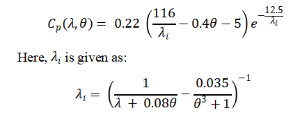
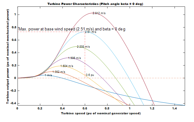
This equation, based on blade element momentum theory, requires iterative calculations for its practical use while providing a reliable estimate of turbine efficiency [15]. Figure 1 shows the mechanical output power of the wind turbine against different wind speeds and a pitch angle of 0. At every different wind speed, the wind turbine provides a unique maximum power output. The torque T generated by the turbine can be quantified as:

- Figure 1: Wind Turbine Characteristics
You can download the Project files here: Download files now. (You must be logged in).
where is the angular velocity of the turbine (rad/s). It is considered that the turbine operates under uniform wind conditions, with its performance parameters optimized for high performance in Uzbekistan’s determined wind source regions [15].
B. DC Generator
DC generators are Universal in small-scale wind energy systems in order to transform the mechanical energy produced by wind turbines to electrical energy. When the wind spins the blades of a turbine it spins the shaft of the DC generator which causes the rotor to spin in a magnetic field producing electricity. As explained in the law of electromagnetic induction described by Faraday this motion generates a voltage between the terminals of the generator.
When the rotor is in motion, magnetic field lines are cut by the armature windings and thus an electromotive force (EMF) is created. The more the rotor rotates the higher is the EMF. The internal resistance and inductance will contribute to the mentioned output voltage and the equation is:

Where, is the terminal voltage, E is the generated EMF, is the armature resistance, is the current, and is the armature inductance. Angular speed of the shaft is also directly proportional to EMF itself which is defined as:
![]()
Where is the EMF constant and is the angular speed. The faster the wind blows the faster the turbine will rotate and the faster the blade spins the bigger the voltage [16].
The electromagnetic torque opposing the movement of the turbine is defined as, . In practice, it is equivalent to the in an optimally designed machines, according to laws of conservation of energy [16].The mechanical dynamics of the system involve the following modeling:
![]()
In which is the mechanical torque provided by the wind, J is inertia and B is the coefficient of friction.
C. Buck Converter Design
The buck converter is critical within the wind power system by converting the fluctuating voltage generated by the DC generator into constant 48V suitable for driving the load. The power to be delivered by the buck converter is 1000W. Figure 2 shows the structural layout of the buck converter which comprises of one semiconductor switch, diode and an inductor.

- Figure 2: Buck Converter
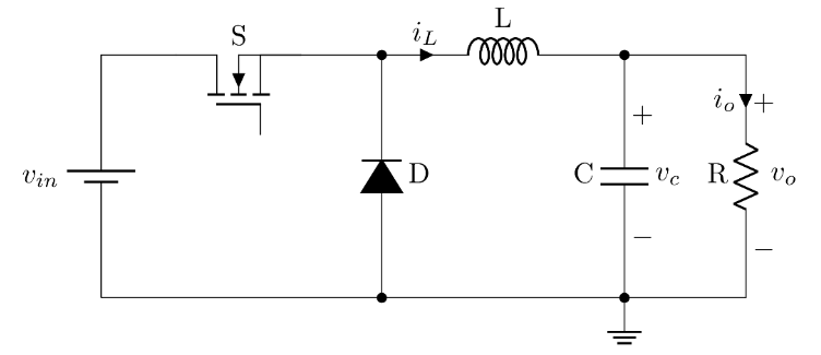
For continuous conduction mode (CCM), output voltage is proportional to voltage and duty cycle D and is given by the following governing equation for output voltage :
Vo = D. Vin
Where: D = ton/Ts : Duty cycle, i.e., switch-on duration over switching period Ts = (1/fs). Vin : Wind generator voltage (variable with variation in wind velocity). The output voltage Vo is regulated at 48V constant with real-time control of duty cycle D with a feedforward controlling mechanism.
The inductor current and capacitor voltage obey the following governing differential equations in CCM
The design specification for the buck converter is given as:
- Input Voltage Range : 168 – 530V
- Load Current : 20.83A
- Inductor Current Ripple 25A
- Output Voltage Ripple : 0.48V
- Inductance (L): 1.10mH
- Capacitance (C): 310µF
- Duty Cycle Range (D):089 to 0.28
- Frequency F:10000Hz
D. Controller Design
The controller going to be utilized is an adaptive neuro-fuzzy inference system (ANFIS). This type of controller combines the strength of both neural network and fuzzy logic to produce an optimal controller capable of adjusting the duty circle based on the wind speed. The controller takes the output voltage of the DC motor as well as the output torque of the wind turbine as input to generate the required duty cycle, to ensure that the output voltage of the buck converter remains the same as well as the power.
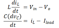
ANFIS training data was generated through simulation using a PI controller. The data recorded where the torque generated by the wind turbine, the voltage generated by the DC motor and the duty cycle from the PI controller. The simulation result using the PI controller will be compared to the Fuzzy controller to observe the performance. The controller for the PI controller is shown in figure 3.

- Figure 3: PI Controller
The PI controller is a feedback controller than ensures that the output voltage is kept at the desired output voltage.
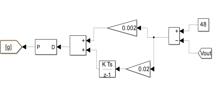
Generator voltage and torque (T) are processed through fuzzification using Generalized Bell membership functions. There are five different membership functions in use. These allow for continuous variable inputs to become translated into linguistic terms, namely “Very High, High, Medium, Low, and Very Low” for both voltage and torque.
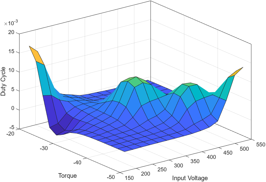
Since the controller we are using is ANFIS, which means that the rules are autogenerated by the neural network during the training. The training lasted for only 1 epoch with minimal error. The ANFIS Structure is shown in Figure 4, clearly showing the two inputs into the controller and the output. From the surface plot in figure 5, we can see how both inputs relates to the output.

- Figure 4 ANFIS system structure

- Figure 5 Surface View of the ANFIS controller
You can download the Project files here: Download files now. (You must be logged in).
IV. Result
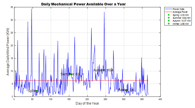
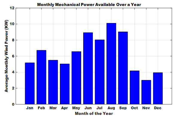
The data collected from NASA was for the entire 2024 calendar year which is a daily wind speed at 50m. Using the equation of the mechanical power generated by the wind turbine, the plot of the daily and monthly power generated was visualize as shown in figure 6 & 7.
From the simulation result, we can see that the wind speed available for the year 2024 is able to supply power to residential household since they are able to generate power more than 1KW. Out of the 366 days data available in the year, only 27 days that the wind speed is unable to generate mechanical power above 1KW. The average power for the year is 6.3KW which is indicated in figure 4 as a straight red line. From the result we can see that more power is produced during the summer and autumn season since most of the points in this season are above the average when compared to spring and winter.
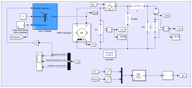
The complete Simulink model is shown in figure 8. The model comprises of the Wind turbine, DC generator, and power electronics converter (Buck Converter). The model will be tested for both constant and variable speed to ensure that the PI and ANFIS controller is able to maintain a constant voltage and power to the output and also compare their performance. For a constant speed simulation, a step input was used as the input speed with an initial speed of 3m/s and final speed 6m/s.

- Figure 6: Daily Mechanical power for the year

- Figure 7: Monthly Wind Power

- Figure 8: Simulink Model
A. Constant Speed
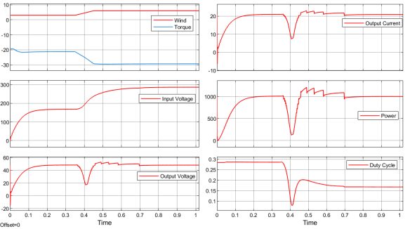
When the wind speed is at 3m/s, the output of the DC generator is 168V. This voltage is now used as input to the buck converter to step it down to 48V. Based on the governing equation of the buck converter, the expected duty cycle should be approximately 0.28. As can be seen from figure 9, the duty cycle is as expected. The same result was observed when the wind speed was stepped to 6m/s
When the wind speed increased to 10m/s, the DC motor voltage increased to 286V. To ensure the output power and voltage remains the same, the PI controller will have to generate a new duty cycle to ensure that the output remains the same. From figure 9, we can see the duty cycle dropping to 0.17 to ensure the output is maintained. The transient shown in the simulation when there is change in the wind speed at 2.5s is as a result of the sudden change in wind speed.

- Figure 9: Constant Simulation Using PI Controller
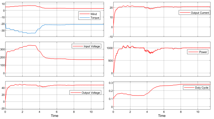
The system was also tested using the ANFIS controller. From figure 10 we can see how accurate, and fast the response is. The system settles at 0.25s compared to the 1.7s when using the PI controller. Also, when the wind speed changed, from 3m/s to 6m/s, the system had a better performance when compared to the PI controller, because of the fast response to changes in wind speed.

- Figure 10: Constant Simulation Using ANFIS
You can download the Project files here: Download files now. (You must be logged in).
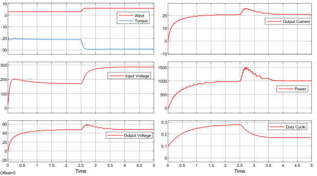
B. Variable speed
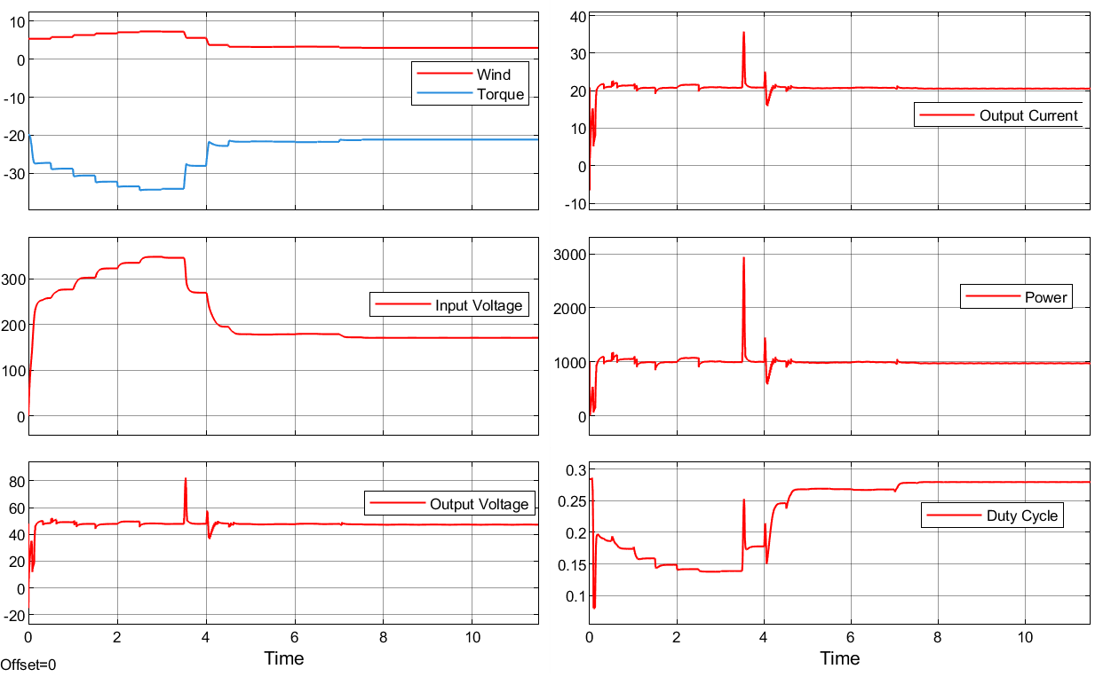
For the variable wind simulation, the first day in the month of October was selected. The simulation result showed that as the speed changes, the DC motor output voltage also changes. Without the aid of a controller these changes will definitely affect the desired output voltage. This variable voltage is fed as input voltage to the buck converter. The PI and ANFIS controller ensure that the duty cycle is updated at all time as the input voltage changes to maintain the desired output voltage and power. As seen from the figure 12 using only the PI controller, the output voltage is maintained at the desired 48V with few ripples due to the changing speed. Also, the current is maintained to ensure the output power is still at the desired value of 1000W. Using the PI controller, we can see how slow the system responds to changes in wind speed.
Using the ANFIS controller on the other hand, the response of the system is more accurate and faster when the wind speed changes. The spikes seen in Figure 12, occurs when there is a sudden sharp change in wind speed there by making the controller to want to quickly adjust itself. This situation can be resolved by implementing a better filtration system that is capable to reduce the spikes in the signal.
The simulation result showed that the ANFIS controller has a better performance when compared to the PI controller, however, the ANFIS controller takes more computing power than the PI controller.

- Figure 11: Variable Simulation Using PI Controller

- Figure 12: Variable Simulation Using Fuzzy Controller
V. Conclusion
The result obtained in this research indicates that wind turbines are a viable solution to decentralize electricity in rural areas of Uzbekistan. The data obtained from NASA showed that there is enough wind power to generate electricity of over 1KW throughout the year, with the annual average of 6.3kW.
This research highlights the prospect of increased efficiency and robustness of wind energy conversion by integrating small-size wind turbine with advanced control systems consisting of a DC generator and a buck converter with the adaptive neuro-fuzzy inference system (ANFIS) controller. Given the growing energy needs of Uzbekistan, the target of renewable energy, and the pursuit of sustainable development, the distributed solution of wind energy is a sustainable way of reducing the usage of fossil fuels, relieving carbon emissions, and increasing the energy security of the country.
References
[1] IEA, “Renewables 2022,” Paris, 2022.
[2] UN, World Population Prospects processed by Our World in Data. “Population, medium projection – UN WPP”. United Nations, “World Population Prospects., 2024.
[3] IRENA, “Energy Profile: Uzbekistan,” Abu Dhabi, 2024.
[4] ADB, “Report and Recommendation of the Presidentto the Board of Directors: Proposed Loan and Partial Credit GuaranteeShamol Zarafshan Energy Foreign Enterprise LimitedLiability CompanyZarafshan Wind Power Project(Uzbekistan),” 2022.
[5] Masdar, Zarafshan Wind Farm, 2023.
[6] GWA, Wind energy resource mapping, 2024.
[7] N. Djalilova and M. Esteban, “Feasibility Study of Hybrid Wind-Solar Stand-Alone Energy System for Remote Regions in Developing Countries: The Case of Post-Soviet Uzbekistan,” International Journal of Sustainable Future for Human Security, vol. 6, p. 3–14, 2018.
[8] N. Matchanov, “Renewable Energy Development in Uzbekistan: Current Status,Problems and Solutions,” Tashkent, 2019.
[9] J. Lee and F. Zhao, “GLOBAL WIND REPORT 2022,” 2022.
[10] A. Abylkasymova, D. Moldokanov, B. Eshchanov, I. Overland, F. Aminjonov and R. Vakulchuk, “Wind Power Potential of the Central Asian Countries,” Central Asia Regional Data Review, vol. 17, 2019.
[11] G. S. Varaganti, N. B. Kampa and S. Vuddanti, “Design and Modelling of Small Scale Wind Turbine for Domestic Power Generation,” in 2022 IEEE 2nd International Conference on Sustainable Energy and Future Electric Transportation (SeFeT), 2022.
[12] N. N. Sadullayev, A. B. Safarov, S. N. Nematov and R. A. Mamedov, “Statistical Analysis of Wind Energy Potential in Uzbekistan’s Bukhara Region Using Weibull Distribution,” Applied Solar Energy, vol. 55, p. 126–132, March 2019.
[13] Z. Lubosny, Wind Turbine Operation in Electric Power Systems: Advanced Modeling, Springer Berlin Heidelberg, 2003.
[14] S. M. Rafaat and R. Hussein, “Power Maximization and Control of Variable-Speed Wind Turbine System Using Extremum Seeking,” Journal of Power and Energy Engineering, vol. 06, p. 51–69, 2018.
[15] B. M. Salih, S. A. Hamoodi and A. N. Hamoodi, “Enhancing the Behavior of Small Scale Wind Turbine Based on Fuzzy Logic System,” Journal Européen des Systèmes Automatisés, vol. 57, p. 147–153, February 2024.
[16] A. Hughes, Electric motors and drives, Fifth edition ed., W. H. Drury, Ed., Kidlington: Newnes, an imprint of Elsevier, 2019.
You can download the Project files here: Download files now. (You must be logged in).
Keywords: ANFIS, Buck converter, Carbon Free Energy, Grid Connected, MATLAB Simulink, Renewable Energy, Smart Grid, Wind turbine


Responses