

Mastering Curvature Continuity in SOLIDWORKS

Learn how curvature continuity (C0–C2) affects surface quality, aesthetics, and manufacturability, with real SOLIDWORKS examples and analysis
1. Introduction: Why Smoothness Matters
Every product you touch tells a story through its surface. Whether it’s a car hood, a perfume bottle, or a gaming mouse, what makes it feel refined is not just its function, it’s the smoothness and flow of its form.
In 3D design, that “feel” comes from curvature continuity, the invisible geometry that defines how two surfaces meet. It’s the difference between a clunky prototype and a professional, manufacturable design.
Yet, many engineers and designers overlook this concept completely. They model, extrude, and fillet, without realizing that their surfaces break visually and physically at a microscopic level.
In this article, we’ll break down what curvature continuity is, how to evaluate it in SOLIDWORKS, and how to create smooth, production-grade surfaces using practical techniques and examples.
2. Understanding Curvature Continuity (C0, C1, and C2)
When two surfaces connect, their relationship defines how light, reflections, and geometry flow across the boundary. This is called continuity, and it’s categorized into three main levels.
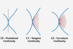
C0 — Positional Continuity
Surfaces touch at an edge, but they are not tangent.
- Reflections break sharply.
- Good for mechanical joints or visible seams
- Poor for aesthetic or aerodynamic designs
Think of a cube, the faces meet, but there’s a visible edge.
C1 — Tangent Continuity
Surfaces touch and share the same tangency direction, resulting in a smoother visual transition.
- Reflections flow continuously, but may still show slight changes in curvature
- Common for most consumer product transitions
Used for parts where you want smooth blending but can tolerate minor reflection changes, e.g., where a mouse top meets its side shell.
C2 — Curvature Continuity
Surfaces touch, share tangency, and also have matching curvature rates (the rate of slope change).
- Reflections and curvature flow seamlessly
- Produces organic, premium-quality surfaces
- Essential for automotive and high-end consumer product design
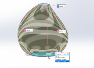
Visual Examples
Image 1 showing types of curvature continuities.
3. Why Curvature Continuity Affects Design Quality
Curvature isn’t just visual, it affects how a product performs, how it’s manufactured, and even how it’s perceived by users.
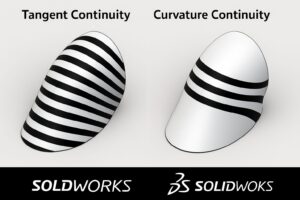
1. Aesthetics
- Surfaces with C2 continuity reflect light uniformly, creating natural highlights and shadows
- Even small discontinuities appear as “kinks” in renderings or real products
According to industrial design studies from Dassault Systèmes, improved surface continuity can reduce post-finishing effort by up to 30%, especially in tooling and mold design.
2. Manufacturability
- Smooth transitions make machining, molding, and polishing easier
- Fewer toolpath direction changes reduce tool wear and time
- C2 surfaces require less manual finishing after CNC machining
3. Aerodynamics and Flow
- Continuous curvature reduces turbulence in aerodynamic surfaces
- Used extensively in automotive and aerospace structures
4. Structural Performance
- Sudden curvature changes can cause localized stress concentrations
- Continuous transitions spread loads evenly across a surface
Image 2 showing light reflection differences on C1 vs. C2 surfaces.
4. Tools in SOLIDWORKS for Curvature Control
Creating curvature-controlled surfaces in SOLIDWORKS involves specific tools and display methods.
A. Boundary Surface
- Found under Insert → Surface → Boundary Surface
- Allows control over tangency or curvature at start and end boundaries
- Best for smooth transitions between complex profiles
Tip: Always set both ends to “Curvature” if your geometry allows, this ensures C2 flow.
B. Filled Surface
- Use when patching holes or blending regions.
- In the PropertyManager, under “Constraints,” choose:
- Contact (C0)
- Tangent (C1)
- Curvature (C2)
- Contact (C0)
- Ideal for repairing small gaps or creating smooth blends between neighboring faces
C. Lofted Surface
- Use multiple guide curves and start/end constraints to maintain continuity
- Helpful for bottle necks, fairings, or wing transitions
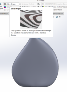
D. Evaluate Tools for Verification
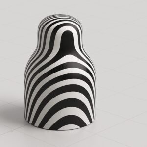
- Zebra Stripes: simulate reflective lines to inspect surface flow.
(View → Display → Zebra Stripes) - Curvature Combs: display curvature magnitude and direction on splines.
- Curvature Analysis: color maps showing curvature variation (Evaluate tab → Curvature).
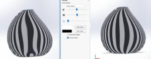
Image 3: Zebra stripes flowing smoothly across a curvature-continuous surface.
5. Practical Example: Designing a Smooth Bottle Body
Let’s apply these principles to a real project, designing a water bottle body with a smooth, elegant form.
Step 1: Define Profiles
- Create two profiles: the bottle base and the neck curve using splines on parallel planes
- Ensure each spline is fully defined and smooth. Avoid unnecessary control points
Step 2: Apply Boundary Surface
- Select the two profiles as main boundaries
- In the PropertyManager, set “Curvature” for both ends
- Use guide curves along the sides to maintain shape symmetry
Step 3: Knit Surfaces
- Combine the created surfaces into one using Surface Knit
- Enable “Try to form solid” if the body is closed

Step 4: Verify Continuity
- Apply Zebra Stripes to inspect reflection flow
- If stripes bend sharply, adjust tangency handles or curvature constraints
- For verification, open Curvature Analysis to check the color gradient across the blend
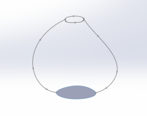
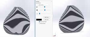
Step 5: Comparison
Create a second version with only Tangent (C1) constraints, and compare:
- Light reflections are inconsistent.
- The model looks cheaper and less “fluid.”
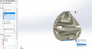
Image 4: Side-by-side comparison: C1 vs. C2 bottle surfaces (Horizontal and vertical stripes)
Outcome
The C2 version will have:
- Continuous reflection flow across the body
- Reduced surface machining issues
- Better appearance in rendering and physical prototypes
6. Advanced Concepts: Taking Continuity Further
For those wanting more depth, curvature control goes beyond just tangency.
1. Gaussian Curvature
Defined as the product of the two principal curvatures:
K=1R1R2K = frac{1}{R_1 R_2}K=R1R21
- K>0K > 0K>0: Convex region (like a sphere).
- K<0K < 0K<0: Saddle shape.
- K=0K = 0K=0: Perfectly flat region.
Use this to evaluate complex surfaces like blends or fairings where double curvature exists.
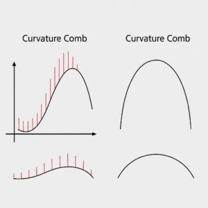
2. Curvature Graphs
In SOLIDWORKS, you can display curvature graphs on splines to visualize smoothness.
- Peaks indicate sharp curvature changes
- Keep comb heights consistent for continuous flow
3. Surface Fairness
Also known as “G2 continuity,” fairness measures the consistency of curvature across large regions.
Use Boundary Surface or Style Spline to control this at a fine level.
Image 5: Curvature comb graph on spline showing smooth transition
7. Common Mistakes and How to Fix Them
| Problem | Cause | Solution |
| Visible reflection breaks | Mismatch of curvature/tangency | Rebuild with “Curvature” constraints |
| Surface fails to knit | Non-coincident edges or gaps | Use “Filled Surface” with curvature boundary |
| Surface warping | Too many spline control points | Simplify spline or use Style Spline |
| Rippled reflections | Uneven curvature comb | Adjust spline weighting and handles |
Additional Tips:
- Always apply curvature analysis before filleting, fillets can mask underlying surface issues.
- Use Repair Face and Check tools before export to ensure surface validity
- Keep curvature transitions simple. Fewer, cleaner splines yield better results.
8. Conclusion: The Geometry of Great Design
Curvature continuity is the unsung hero of exceptional product design. It determines not just how a part looks, but how it feels, how it performs, and how easily it can be manufactured.
In SolidWorks, mastering curvature means mastering control over form, function, and perception. Whether you’re designing a bottle, a car hood, or an aircraft fairing, a smooth surface transition tells the world you care about precision and detail.
References
- Dassault Systèmes SOLIDWORKS Help: “Surface Continuity and Evaluation Tools.”
- Autodesk University (2021). Curvature Continuity Explained in CAD Modeling.
- Design World Magazine (2022). Surface Smoothness and Manufacturing Efficiency.
- Koren, N. P. (2020). Mathematics for Curves and Surfaces.


Responses