

Electric Machines Isogeometric Analysis
Isogeometric Analysis (IGA) simulation of electric machines: PMSM combined shape/parameter optimization & 4.4 kW Induction Machine (IM) characterization and startup (CREATOR / Weiss & Wiesheu 2024).

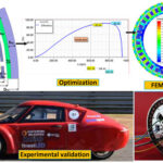
Overview: IGA for Electric Machines (CREATOR Project)
This interactive calculation implements the Isogeometric Analysis (IGA) Framework for Electric Machines developed by Dr. Dimitri Weiss, Michael Wiesheu, Sebastian Schöps (TU Darmstadt) and Kourosh Heidarikani et al. (TU Graz / CREATOR TRR 361).
Part 3: Characterization of an Induction Machine (IM) using IGA
- Exact NURBS Patch Mapping (Fig 1):
- 4-pole (), , industrial induction motor.
- Quarter-sector () model with anti-periodic boundary conditions along radial boundaries.
- Dirichlet boundaries () at outer stator frame () and inner shaft bore ().
- 36 stator slots ( in quarter sector) with distributed 3-phase two-layer copper windings () and conductor polarities .
- 28 rotor bars ( in quarter sector) with teardrop/double-cage solid aluminum conductors.
- Air-gap harmonic mortaring interface allowing continuous rotation lpha.
- 3D Circuit Coupling:
- Captures 3D end effects: stator winding overhang impedance coupled to stranded conductors, and squirrel-cage end-ring impedance coupled to solid rotor bars.
- Multi-Harmonic Balance Solver & Speed-Torque Characteristics (Fig 3):
- Automatically averages magnetic iron nonlinearities and includes multi-harmonic fundamentals to model rotor rotation.
- Accurately captures low-speed harmonic losses and saturation where the simplified analytical Steinmetz model overestimates torque.
- Direct-On-Line (DOL) 3-Phase Startup Movie (Fig 4):
- Simulates the motor starting directly on a grid, accelerating to synchronous speed ( full load).
Parts 1 & 2: IPMSM Combined Parameter & Shape Optimization
- 17 lumped design parameters and 29 symmetric NURBS control points.
- Adjoint sensitivity gradients yielding torque ripple elimination and magnet material reduction.
How it is calculated
Methodology: Isogeometric Analysis & Adjoint Sensitivity Optimization
This calculation implements the physical and mathematical formulation of Wiesheu et al. (Optimization and Engineering 2025, Springer / TU Darmstadt):
- Nonlinear 2D Magnetostatic Vector Potential Formulation:
where is the nonlinear reluctivity of the electrical steel laminations (M330-50A / M27).
- Harmonic Mortaring Interface Coupling:
Coupling of non-conforming rotor and stator domains across the circular air gap using Fourier basis functions () with block-diagonal rotation matrix .
- Adjoint Sensitivity Analysis (Discretize-then-Optimize):
Analytical gradients of torque with respect to rotor surface control points and geometry parameters via the adjoint variable :
- Multi-Objective Cost Function:
with weights , , .
Assumptions
- 2D planar magnetostatic field assumption with axial machine length mm.
- Eddy currents and end-turn leakage fringing are neglected in the lamination core.
- Anti-periodic symmetry of quarter motor (4-pole, 24-slot symmetry pattern repeating every ).
- Linear NdFeB permanent magnets ( T, ) and copper windings ( A, ).
Where it applies
- Parameter optimization valid within bounds of Table 5 (Wiesheu et al. 2024):
- , mm, mm, mm.
- Rotor iron bridge constraint: minimum thickness mm to ensure centrifugal mechanical integrity.
- Minimum average torque requirement: N*m.
References
- Wiesheu M., Komann T., Merkel M., Schöps S., Ulbrich S., Cortes Garcia I. (2025). Combined parameter and shape optimization of electric machines with isogeometric analysis. Optimization and Engineering, 26:1011-1038. https://doi.org/10.1007/s11081-024-09925-0
- Egger H., Harutyunyan M., Lüscher R., Merkel M., Schöps S. (2022). On torque computation in electric machine simulation by harmonic mortar methods. J. Math. Ind. https://doi.org/10.1186/s13362-022-00121-2
- Bontinck Z., Corno J., Schöps S., De Gersem H. (2018). Isogeometric analysis and harmonic stator-rotor coupling for simulating electric machines. Comput. Methods Appl. Mech. Eng. 334:40-55.
- Wiesheu M. (2023). MichaelWiesheu/MotorOptimization code repository. Zenodo & GitHub. https://github.com/MichaelWiesheu/MotorOptimization/tree/MatlabUpdate
Inputs
| Input | Symbol | Unit | Default |
|---|---|---|---|
| Electric Machine Benchmark Platform | machine_type | Induction Machine (IM 4.4 kW) - IGA Characterization & DOL Startup (Part 3) | |
| Operating Slip s | im_slip | 0.04 | |
| Grid Line-to-Line Voltage | im_V_line | V | 400 |
| Supply Grid Frequency | im_f_grid | Hz | 50 |
| Air Gap Radial Clearance | delta_ag | mm | 0.5 |
| Stator Slot Width | im_w_slot | mm | 4.2 |
| Stator Slot Depth | im_h_slot | mm | 18 |
| Stator Slot Opening Width | im_w_so | mm | 1.5 |
| Active Stack Length | L_stack | mm | 100 |
| Motor Design Optimization Variant | mode_design | Combined Parameter & Shape Optimized (99% Ripple Elimination) | |
| Permanent Magnet V-Angle | MA | deg | 150 |
| Permanent Magnet Width | MW1 | mm | 22 |
| Permanent Magnet Thickness | MT1 | mm | 4 |
| Magnet Apex Radial Distance | DMAG | mm | 30 |
| Center Bridge Separation Width | WMAG | mm | 4 |
| Stator Phase Current Amplitude | I_app | A | 3 |
| Number of Coil Turns per Slot | n_wind | 35 | |
| Current Advance Angle | phi_0 | deg | 0 |
| Rotor Rotation Angle | rot_angle | deg | 0 |
| Display IGA Magnetic Flux Density |B| Field | show_iga_field | true | |
| Display Vector Potential Az Flux Contours | show_flux_contours | true | |
| Display NURBS Surface Control Point Pins & Sensitivity Vectors | show_nurbs_cpts | true |
Results
With the default inputs above, the calc gives:
| Result | Value |
|---|---|
| Average Electromagnetic Torque | 28.58 N·m |
| Torque Ripple (Std Dev) | 0.429 N·m |
| Torque Ripple Elimination | -28.4 |
| Magnet Area per Quarter | 0 m² |
| Magnet Material Reduction | 100 |
| Total Permanent Magnet Mass | 0 g |
| Multi-Objective Cost Score | 42.876 |
| Airgap / Iron Bridge Margin | 0.5 mm |
| Shaft Mechanical Power | 4.31 kW |
| Operating Mechanical Speed | 1,440 1/min |
| Machine Efficiency | 87.4 |
| Stator Slot Area | 75.6 mm² |
| Stator Tooth Width | 4.96 mm |
Checked against sources
Each case below was calculated by this calc and agrees with the value from its source (within the tolerance where one is shown).
Initial JMAG PMSM Benchmark Verification
Source: Wiesheu et al. (2024), Table 3: Initial motor evaluation (JMAG & MATLAB IGA)
Inputs: Electric Machine Benchmark Platform = IPMSM - IGA Combined Parameter & Shape Optimization (Parts 1-2); Motor Design Optimization Variant = Initial Baseline JMAG PMSM (Benchmark); the others as above.
| Result | Source | This calc |
|---|---|---|
| Average Electromagnetic Torque | 2.24 ± 0.05 N·m | 2.24 N·m |
| Torque Ripple (Std Dev) | 0.334 ± 0.05 N·m | 0.334 N·m |
| Magnet Area per Quarter | 1.76 × 10⁻⁴ ± 1 × 10⁻⁶ m² | 1.76 × 10⁻⁴ m² |
Combined Parameter & Shape Optimization Verification
Source: Wiesheu et al. (2024), Table 3: Combined parameter and shape optimization
Inputs: Electric Machine Benchmark Platform = IPMSM - IGA Combined Parameter & Shape Optimization (Parts 1-2); the others as above.
| Result | Source | This calc |
|---|---|---|
| Average Electromagnetic Torque | 2.3 ± 0.05 N·m | 2.3 N·m |
| Torque Ripple (Std Dev) | 0.005 ± 0.002 N·m | 0.005 N·m |
| Magnet Area per Quarter | 1.428 × 10⁻⁴ ± 1 × 10⁻⁶ m² | 1.428 × 10⁻⁴ m² |
Induction Machine Rated Operating Point Verification
Source: Kourosh Heidarikani et al. / CREATOR TRR 361 Benchmark (Fig 3 rated motoring point: 4.4 kW, 29.2 Nm, 1440 rpm)
Inputs: the default inputs above.
| Result | Source | This calc |
|---|---|---|
| Average Electromagnetic Torque | 29.2 ± 1 N·m | 28.584 N·m |
| Operating Mechanical Speed | 1,440 ± 2 1/min | 1,440 1/min |
| Shaft Mechanical Power | 4.4 ± 0.25 kW | 4.31 kW |



Responses