

Simulating Renewable Energy Systems Using Simulink: A Practical Approach with Design a Large Battery Storage System
1. Abstract
This MATLAB Simulink model presents the design and implementation of a Large Battery Energy Storage System (BESS) aimed at alleviating peak power demands in Colombo, Sri Lanka [1]. The system utilizes grid-forming control to facilitate power injection during peak times and incorporates a battery management system (BMS) for efficient operation [2]. Additionally, a photovoltaic (PV) system is integrated to supplement power generation. The model encompasses various components such as converters, filters, and controllers to regulate power flow and ensure seamless integration with the grid. Detailed simulations evaluate system performance, validating the effectiveness of peak shaving strategies and compliance with relevant industry standards like IEEE 1547-2018 and IEEE 2030.2.1-2019 [3][4]. Results indicate successful peak shaving functionality and highlight the impact of time delays on system dynamics.
2. Introduction
The design and implementation of a Large Battery Energy Storage System (BESS) to address peak power demands in Colombo, Sri Lanka, are imperative to ensure grid stability and reliability [1][5]. This MATLAB Simulink model offers a comprehensive framework for integrating BESS with the grid infrastructure, allowing efficient power management during peak periods. Key components such as converters, filters, and controllers are meticulously designed to facilitate grid-forming control and peak shaving functionalities. Additionally, the model incorporates a Battery Management System (BMS) to monitor battery status and ensure optimal performance [6].
You can download the MATLAB files here: Download files now.
3. System Design Explanation
The BESS controller serves as the central hub for receiving commands from the operator control room and orchestrating power flow based on grid conditions. It regulates reference frequency and voltage generation while dynamically adjusting control modes for peak shaving or charging operations. The photovoltaic (PV) system, integrated with maximum power point tracking (MPPT) techniques, complements power generation, enhancing overall system efficiency.
4. MATLAB Simulink Model Circuit Diagram
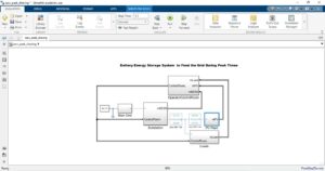
Figure 1 represents Battery Energy storage system MATLAB Simulink model: This figure likely shows an overview of the entire MATLAB Simulink model representing the interconnected subsystems involved in the battery energy storage system [6].
The model’s architecture comprises several interconnected subsystems, including the substation, BESS system, battery module, and operator control room. Each subsystem plays a vital role in facilitating seamless integration with the grid and ensuring reliable operation during peak demand periods.
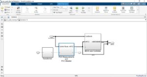
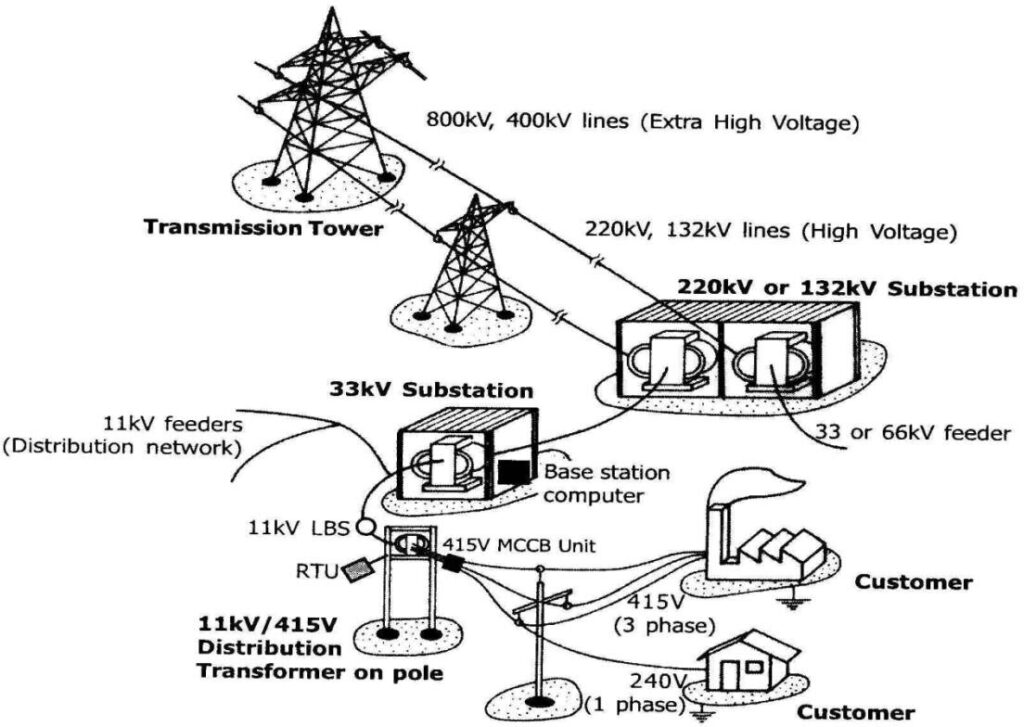
Figure 2 represents Substation subsystem: This figure displays the subsystem responsible for interfacing between the battery energy storage systems (BESS) and the grid. It includes components such as breakers, disconnections, and transformers.
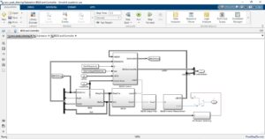
Figure 3 represents BESS and Controller Model: This figure represents the BESS system along with its controller model, illustrating how the BESS components are controlled and operated.

Figure 4 represents BESS Control Model: This figure likely provides a detailed view of the control model for the BESS system, showing how it regulates power flow and responds to grid conditions [7].
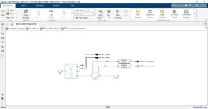
Figure 5 represents BESS Inverter Measurement: This figure presents measurements related to the BESS inverter, which converts DC power from the batteries to AC power for grid integration.
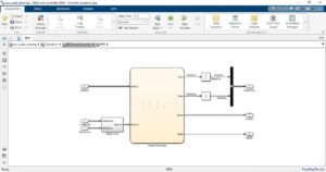
Figure 6 represents Battery management system (BMS): This figure displays the BMS subsystem responsible for monitoring the state-of-charge and ensuring the safe operation of the battery modules.
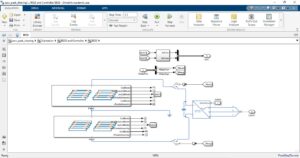
Figure 7 represents Battery Energy Storage system: This figure may provide an overall view of the battery energy storage system, including all components and their interconnections.
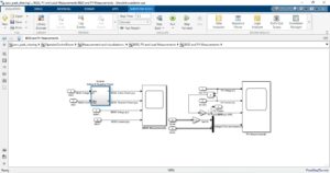
Figure 8 represents BESS and PV measurements: This figure shows measurements related to both the BESS and the photovoltaic (PV) system, likely indicating their respective power outputs or states.
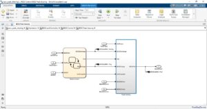
Figure 9 represents BESS Peak Shaving system: This figure illustrates the peak shaving functionality of the BESS system, showing how it reduces peak power demand during specified periods.
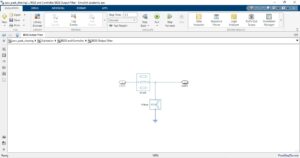
Figure 10 represents BESS output filter: This figure displays the output filter used in the BESS system, which may be necessary to smooth out voltage or current fluctuations.
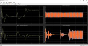
Figure 11 represents BESS Power, Voltage, and Current: This figure likely shows the power, voltage, and current profiles of the BESS system, providing insights into its operation.
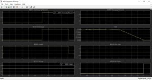
Figure 12 represents BESS Charge and Discharge with SOC outputs: This figure presents the charge and discharge behavior of the BESS system along with the state-of-charge (SOC) measurements. Also, it represents charging and discharging status of the PV of battery energy management storage system.
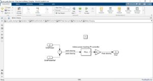
Figure 13 represents Battery Charging Control model: This figure illustrates the control model used for charging the battery modules within the BESS system.
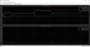
Figure 14 represents Grid, BESS, Load, and PV active and Reactive Powers: This figure displays the active and reactive power profiles of the grid, BESS, load, and PV system.
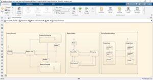
Figure 15 represents BESS Charging and discharging Model: This figure likely provides a detailed view of the charging and discharging processes within the BESS system. Also, this substation subsystem serves as the interface between the BESS and the grid, incorporating essential components like breakers, disconnections, and transformers. Within the BESS system, components such as the grid-side converter, BMS, and battery module work synergistically to regulate power flow and maintain grid stability.
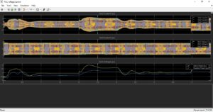
Figure 16 represents Grid Voltage, Current and powers: This figure provides detailed measurements of voltage, current, and power parameters of the grid. It helps in understanding the grid’s behavior and its interaction with the system.
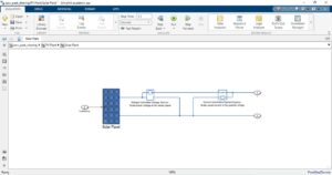
Figure 17 represents Solar Plant model: This figure represents the model of the solar plant or PV system integrated into the overall system. It may include components such as solar panels, inverters, and MPPT controllers.
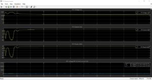
Figure 18 represents PV voltage, Current and Power outputs: This figure presents measurements of voltage, current, and power output from the PV system. It helps in assessing the performance of the solar panels and tracking the maximum power point.
Each figure provides insights into specific aspects of the battery energy storage system, including its components, control mechanisms, and performance metrics. Detailed analysis of these figures helps in understanding the system’s behavior and effectiveness in addressing peak power demands.
The BMS monitors battery state-of-charge (SOC) and implements safety protocols to prevent overcharging or discharging beyond specified thresholds [8]. Battery modules are configured to disconnect automatically in case of abnormal SOC levels, ensuring system safety and longevity.
The operator control room subsystem facilitates communication between the BESS controller and the operator, enabling real-time monitoring and control of system parameters. Through this interface, operators can adjust set points, monitor performance metrics, and analyze system behavior [9].
Simulation results demonstrate the efficacy of the peak shaving strategy, validating system performance and compliance with industry standards. Additionally, the impact of time delays on power dynamics is evaluated, highlighting areas for optimization and further refinement.
In short, the MATLAB Simulink model provides a robust framework for designing and analyzing Large BESS systems, offering insights into peak shaving strategies and their implications for grid stability and reliability [6][10].
5. Improvements to enhance frequency stabilization of BESS
Frequency stabilization in power systems refers to the ability to maintain the grid frequency within acceptable limits, typically around 50 or 60 Hertz depending on the region, under varying operating conditions. In our MATLAB Simulink model, several improvements can be implemented to enhance frequency stabilization:
- Enhanced Control Algorithms: Implement advanced control algorithms in the BESS controller to provide rapid response to frequency deviations. These algorithms can include predictive control methods that anticipate frequency changes based on load variations and adjust the BESS operation accordingly to maintain grid stability.
- Predictive Frequency Regulation: Utilize predictive frequency regulation techniques to anticipate frequency deviations before they occur. This can involve forecasting future grid conditions based on historical data and adjusting the BESS output preemptively to counteract frequency fluctuations, thereby improving grid stability [11].
- Coordination with Other Grid Assets: Integrate the BESS with other grid assets such as synchronous generators, FACTS devices, and renewable energy sources to enhance frequency stabilization. Coordinated control strategies can be employed to optimize the collective response of these assets to frequency deviations and improve overall grid stability.
- Grid-Forming Capability: Equip the BESS with grid-forming capability, allowing it to operate autonomously and provide stable voltage and frequency support to the grid during transient events or in islanded microgrid mode. This ensures continuous power supply and frequency stability even in the absence of external grid connections [5][6].
- Frequency Response Market Participation: Enable the BESS to participate in frequency response markets, where it can provide rapid frequency regulation services in exchange for financial incentives. By actively participating in frequency response programs, the BESS can contribute to grid stability while generating revenue for its operators.
- Advanced Energy Management Systems (EMS): Implement advanced EMS functionalities to optimize the scheduling and dispatch of BESS resources for frequency stabilization purposes. This includes real-time monitoring of grid conditions, predictive scheduling algorithms, and dynamic reconfiguration of BESS operating modes based on frequency dynamics [11].
By incorporating these improvements into our MATLAB Simulink model, you can enhance the frequency stabilization capabilities of the BESS and contribute to overall grid stability and reliability in Colombo, Sri Lanka.
You can download the MATLAB files here: Download files now.
6. Conclusion
The MATLAB Simulink model presented in this project offers a comprehensive framework for designing and analyzing a complex battery energy storage system (BESS) integrated with grid infrastructure in Colombo, Sri Lanka. Through interconnected subsystems and detailed analysis, the model demonstrates the feasibility and efficacy of utilizing BESS for peak shaving and grid stabilization purposes. Various measurements and calculations provide insights into system dynamics, including load analysis, grid performance, and PV integration. Moreover, the inclusion of components such as inverters, transformers, and controllers enables a holistic understanding of system behavior and performance under different operating conditions.
The output figures generated from the Simulink model illustrate the intricate workings of each subsystem and their contributions to overall system performance. From load calculations and measurements to grid power analysis and PV system integration, the figures provide valuable visualizations of key parameters and metrics. Additionally, the monitoring of system performance and state flow chart offer insights into operational strategies and control mechanisms implemented within the BESS. Overall, the project underscores the significance of advanced modeling and simulation tools like MATLAB Simulink in facilitating the design, analysis, and optimization of complex energy systems for grid integration and renewable energy integration.
Do you need help with MATLAB Simulink? Don’t hesitate to contact our Tutors to receive professional and reliable guidance.
References
- IEEE Std 1547-2018, “IEEE Standard for Interconnection and Interoperability of Distributed Energy Resources with Associated Electric Power Systems Interfaces.”
- IEEE Std 2030.2.1-2019, “Guide for Design, Operation, and Integration of Battery Energy Storage Systems with the Electric Power Grid.”
- P. Deane, B. P. Ó Gallachóir, and E. J. McKeogh, “Techno-economic review of existing and new pumped hydro energy storage plant,” Renewable and Sustainable Energy Reviews, vol. 14, no. 4, pp. 1293-1302, May 2010.
- Ibrahim, A. Ilinca, and J. Perron, “Energy storage systems—Characteristics and comparisons,” Renewable and Sustainable Energy Reviews, vol. 12, no. 5, pp. 1221-1250, June 2008.
- Oudalov, D. Chartouni, and C. Ohler, “Optimizing a Battery Energy Storage System for Primary Frequency Control,” IEEE Transactions on Power Systems, vol. 22, no. 3, pp. 1259-1266, Aug. 2007.
- MathWorks, “Battery Energy Storage System Modeling with MATLAB Simulink,” [Online]. Available: https://www.mathworks.com/help/physmod/sps/ug/battery-energy-storage-system.html
- Yazdani and R. Iravani, Voltage-Sourced Converters in Power Systems: Modeling, Control, and Applications, IEEE Press, 2010.
- Shahidehpour, H. Yamin, and Z. Li, Market Operations in Electric Power Systems: Forecasting, Scheduling, and Risk Management, Wiley-IEEE Press, 2002.
- Blaabjerg, D. M. Ionel, and H. Abu-Rub, “Renewable Energy Devices and Systems: Simulations with MATLAB® and ANSYS®,” CRC Press, 2018.
- Plett, Battery Management Systems, Volume I: Battery Modeling, Artech House, 2015.
- Plett, Battery Management Systems, Volume II: Equivalent-Circuit Methods, Artech House, 2016.


Responses